

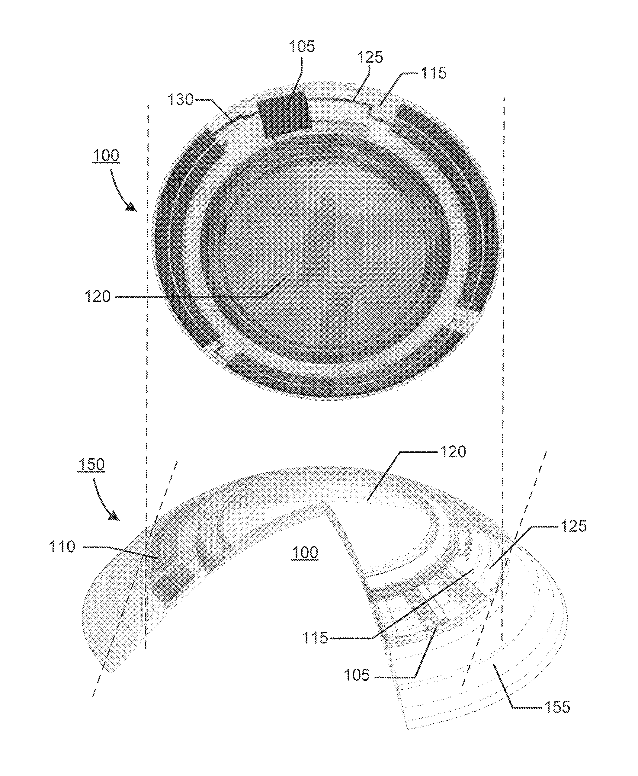
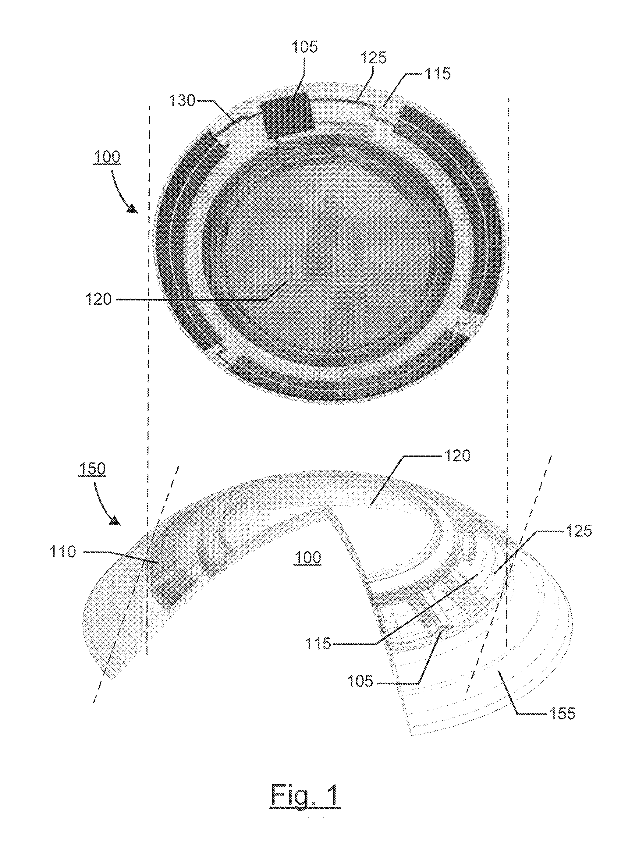
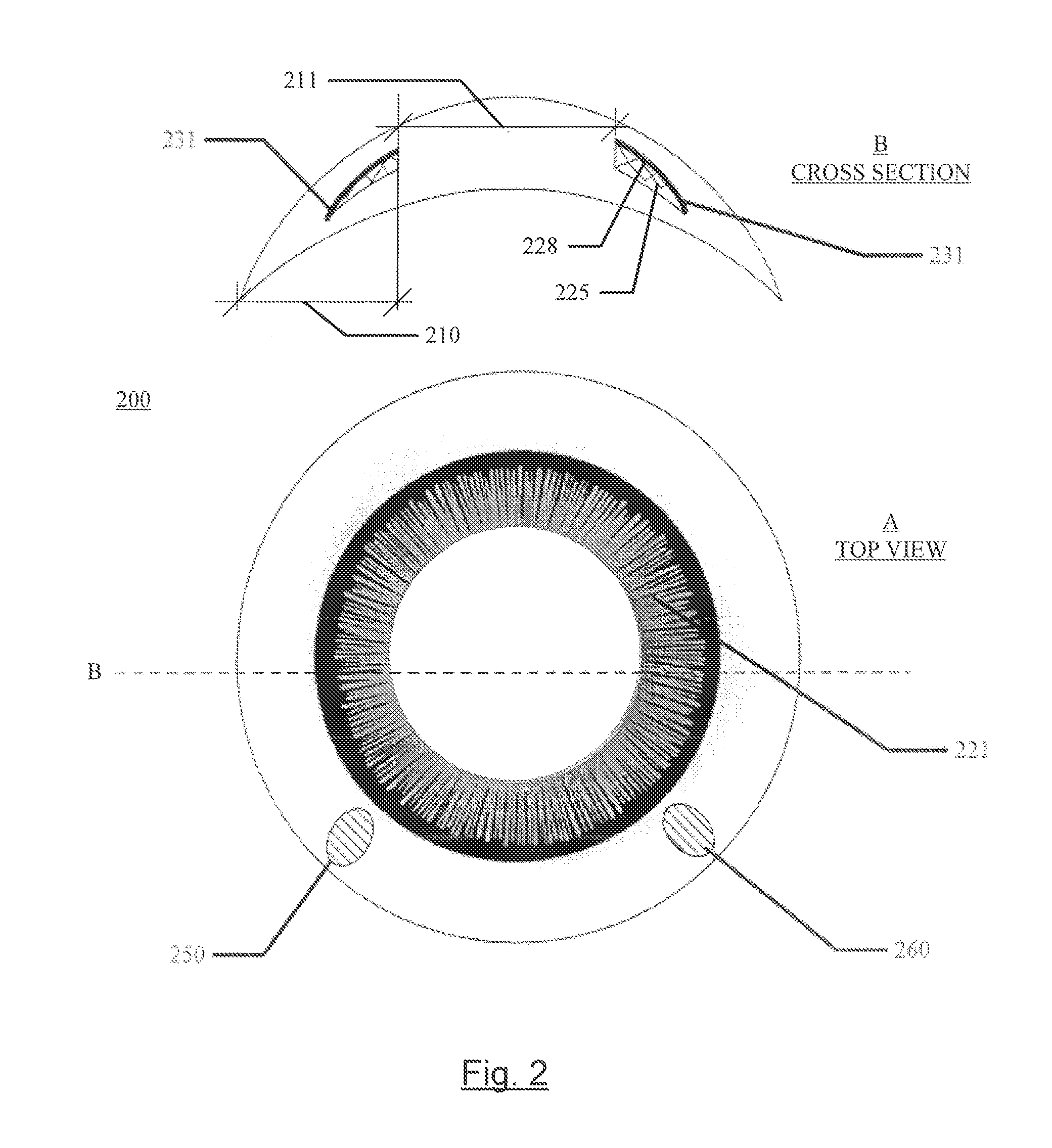
Method and ophthalmic device for providing visual representations to a user
- Summary
- Abstract
- Description
- Claims
- Application Information
AI Technical Summary
Benefits of technology
Problems solved by technology
Method used
Image

Examples
Embodiment Construction
Glossary
[0027]In this description and claims directed to the presented invention, various terms may be used for which the following definitions will apply:
[0028]Electro-wetting on Dielectric or EWOD: as used herein refers to a class of devices or a class of portions of devices where a combination of immiscible fluids or liquids, a surface region with defined surface free energy and an electro-potential field are present. Typically, the electro-potential field will alter the surface free energy of the surface region, which may alter the interaction of the immiscible fluids with the surface region.
[0029]Energized: as used herein refers to the state of being able to supply electrical current to or to have electrical energy stored within.
[0030]Energy: as used herein refers to the capacity of a physical system to do work. Many uses within this invention may relate to the said capacity being able to perform electrical actions in doing work.
[0031]Energy Source: as used herein refers to a d...
PUM
 Abstract
Description
Claims
Application Information