Polarization Grating Stack

Inactive Publication Date: 2014-09-18
RAYTHEON CO
View PDF0 Cites 11 Cited by
  • Summary
  • Abstract
  • Description
  • Claims
  • Application Information

AI Technical Summary

Benefits of technology

[0028]Accordingly, an array of phase-locked sub-apertures with adaptive correction of phase distortions incorporated directly into each sub-aperture (such as an APPLE system) will perform better with FSOPAs replacing a PZT fiber actuator (it should be noted that one FSOPA is needed for each dimension.)
[0029]Replacement of the PZT fiber actuator with a FSOPA eliminates mechanical motion in the APPLE system, resulting in a true non-mechanical, all-electronic system, and a much more robust system. The FSOPA will be at least as robust as a conventional OPA, which from tests is operable to hundreds of g's.
[0030]Furthermore, one possible issue with the current APPLE system is the demonstrated presence of higher order modes in the over-moded delivery fiber. These modes move around within the fiber core when the fiber is bent, change relative phases, and cause the output beam to both deform and move about, and that motion appears to preclude meeting the pointing accuracies desired. Replacement of the PZT fiber actuator with an FSOPA means that the fiber no longer needs to move and can be firmly anchored, presumably significantly reducing mode motions.
[0031]A fixed feed-point also allows the APPLE system to be fed by free-space lasers; thus, APPLE-type systems will no longer restricted to fiber lasers. Although fiber lasers are preferred in one sense because of their higher efficiencies, other laser types do offer other potential advantages, and new APPLE designs will allow tradeoffs to be made. As one example, a so-called Semi-Guiding High Aspect Ratio Core (SHARC) laser under development at Raytheon Space and Airborne Systems (SAS), El Segundo, Calif. 90245, USA offers an alternate path to mitigation of stimulated Brillioun scatter (SBS) because the effective core size is much larger than even the over-moded 25 micron core fibers currently used in APPLE. If the current SBS mitigation approach taken by RIFL (phase modulation at

Problems solved by technology

Faster slewing results in higher slew loss level

Method used


Image

  • Polarization Grating Stack
  • Polarization Grating Stack
  • Polarization Grating Stack

Examples


Example

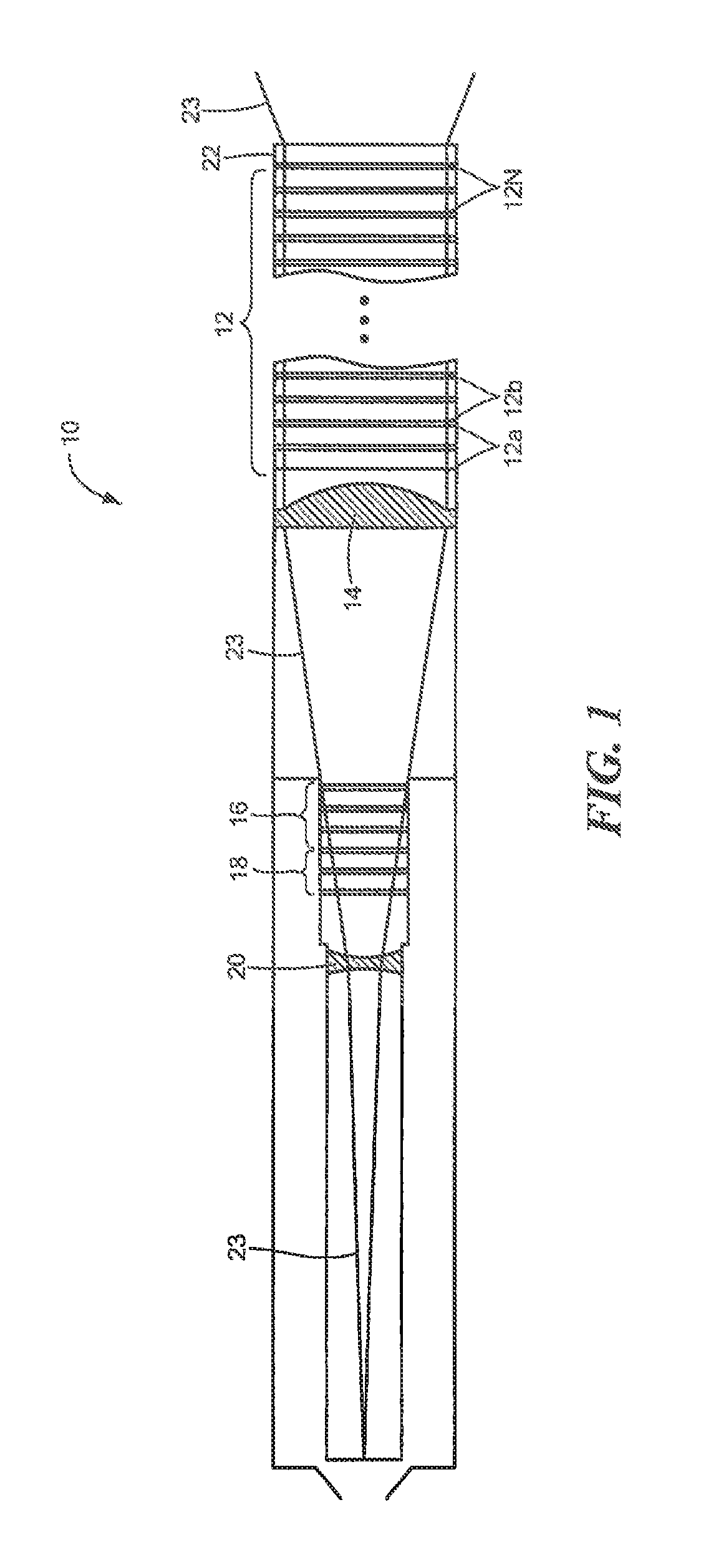
[0074]Described herein is the use of a fast-scanning optical phase array (FS OPA) within an electronic beam-steering-based aperture suitable for use in a system such as the Adaptive Photonically Phase-Locked Elements (APPLE) system, for example.

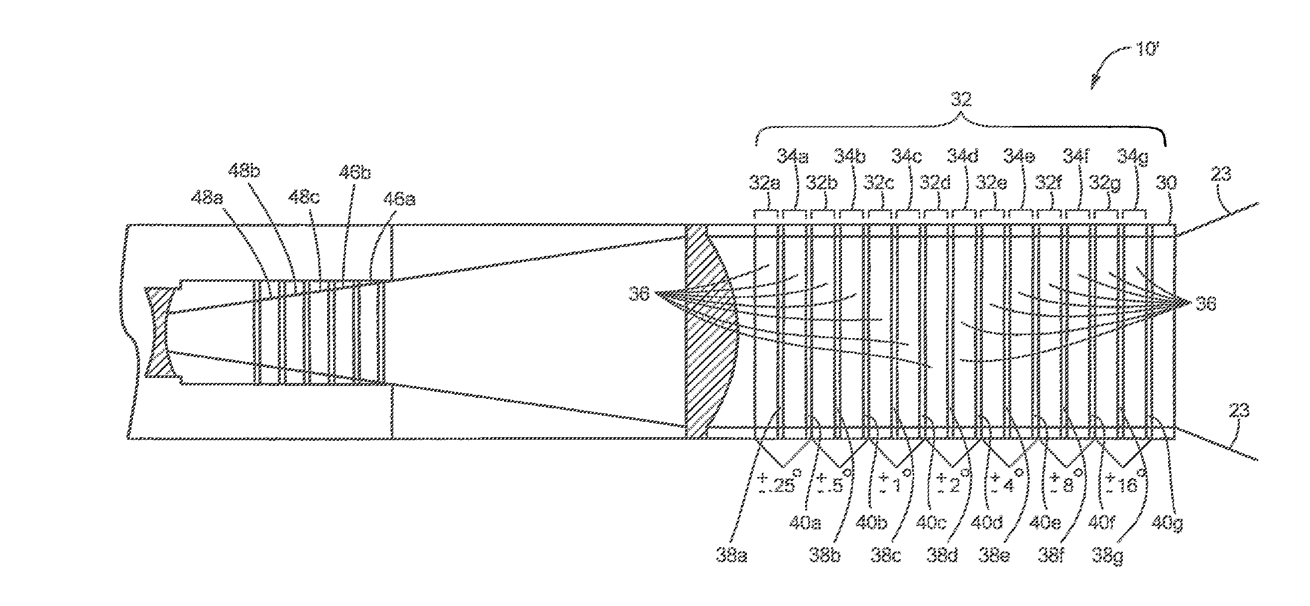
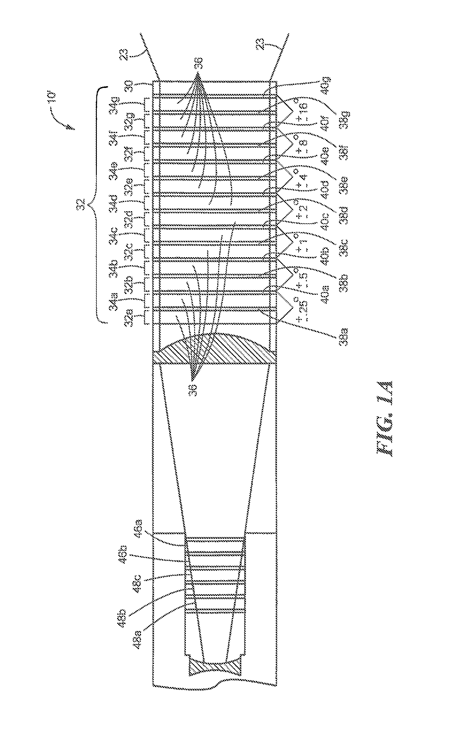
[0075]Also described is a stack of polarization gratings (PGs), each controlled by a liquid-crystal wave plate which may be used in the APPLE system.

[0076]Before describing a fast-scanning optical phase array and a polarization grating architecture, some terminology is defined. As used herein, the term “aperture module” or more simply “aperture” to an optical train having one or more OPA devices, a polarization grating (PG) stack having at least some interleaved PG elements, an adaptive optics (AO) portion, coarse OPAs and one or more half wave plates. One exemplary aperture is a modified APPLE architecture referred to as an “APPLEt.” The terms “composite aperture,”“optical phased-array” or more simply “array” refer to a plurality of aperture...


PUM


Abstract

A stack of polarization gratings each having a grating pitch, the stack having a first end and a second end and, the polarization grating stack including N stages wherein one or more of the N stages in the stack comprise a first set of gratings which direct an incident beam through angles lying substantially in a first plane and one or more of the N stages in the stack comprise a second set of gratings which direct an incident beam through angles lying substantially in a second, different, plane lying at an angle relative to the first plane and wherein each of the N stages provide one of a plurality of deflection angles and wherein the N stages are arranged such that a stage having the smallest deflection angle is nearest the first end of the stack and a stage having the largest deflection angle is nearest the second end of the stack and wherein the deflection angles of the gratings in each set are chosen such that the grating pitch of each grating is at least one of: substantially twice the grating pitch of another member of the set; or substantially one-half the grating pitch of another member of the set.

Description

CROSS REFERENCE TO RELATED APPLICATIONS[0001]This application is a continuation of co-pending application of U.S. application Ser. No. 13 / 250,111, filed Sep. 30, 2011, which claims the benefit of U.S. Provisional Application No. 61 / 389,015, filed Oct. 1, 2010, which applications are hereby incorporated by reference in their entireties.FIELD OF THE INVENTION[0002]The system and techniques described herein relate generally to optical phased arrays and more particularly to steering a beam of an optical phased array.BACKGROUND OF THE INVENTION[0003]As is known in the art, there is a desire to provide an optical system capable of transmitting, receiving, and rapidly steering spatially phased optical energy and images, such a system having a composite aperture comprising multiple individual apertures (i.e., the composite aperture is an array of apertures) each of each should be transmissive.[0004]One such system which includes an array of small phase-locked apertures with adaptive correct...

Claims


Application Information

Patent Timeline
IPC IPC(8): G02F1/29G02B5/30
CPCG02B5/3041G02F1/292
Inventor DORSCHNER, TERRY A.SMITH, IRL W.
Owner RAYTHEON CO
Why Eureka
Try Eureka