Lens assembly and method for assembling the same

a technology of lens assembly and lens barrel, which is applied in the field of optical elements, can solve the problems of inability to meet the demand of portability and increase the thickness of the lens assembly, and achieve the effect of reducing the thickness of the side walls of the lens barrel and the base, and reducing the assembling time of the lens assembly

Active Publication Date: 2014-09-18
HIMAX TECH LTD
View PDF1 Cites 1 Cited by
  • Summary
  • Abstract
  • Description
  • Claims
  • Application Information

AI Technical Summary

Benefits of technology

[0019]Since the lens barrel and the base are connected each other by smooth surface(s) rather than screw portions, the thickness of side walls of the lens barrel and the base can be reduced. Additionally, since the lens barrel can be slid to a predetermined position in the base by directly applying a trust force thereon, instead of by rotating, the assembling time of the lens assembly is further reduced.

Problems solved by technology

Recently, size reduction is a trend for portable electronic products; however, the screw portions may cause an increase in thickness of the lens assembly which cannot satisfy the demand of portability.

Method used


Image

  • Lens assembly and method for assembling the same
  • Lens assembly and method for assembling the same
  • Lens assembly and method for assembling the same

Examples


Embodiment Construction

[0025]Several exemplary embodiments of the application are described with reference to FIGS. 1 through 6, which generally relate to the generation of a secret key. It is to be understood that the following disclosure provides various different embodiments as examples for implementing different features of the application. This description is made for the purpose of illustrating the general principles of the invention and should not be taken in a limiting sense.

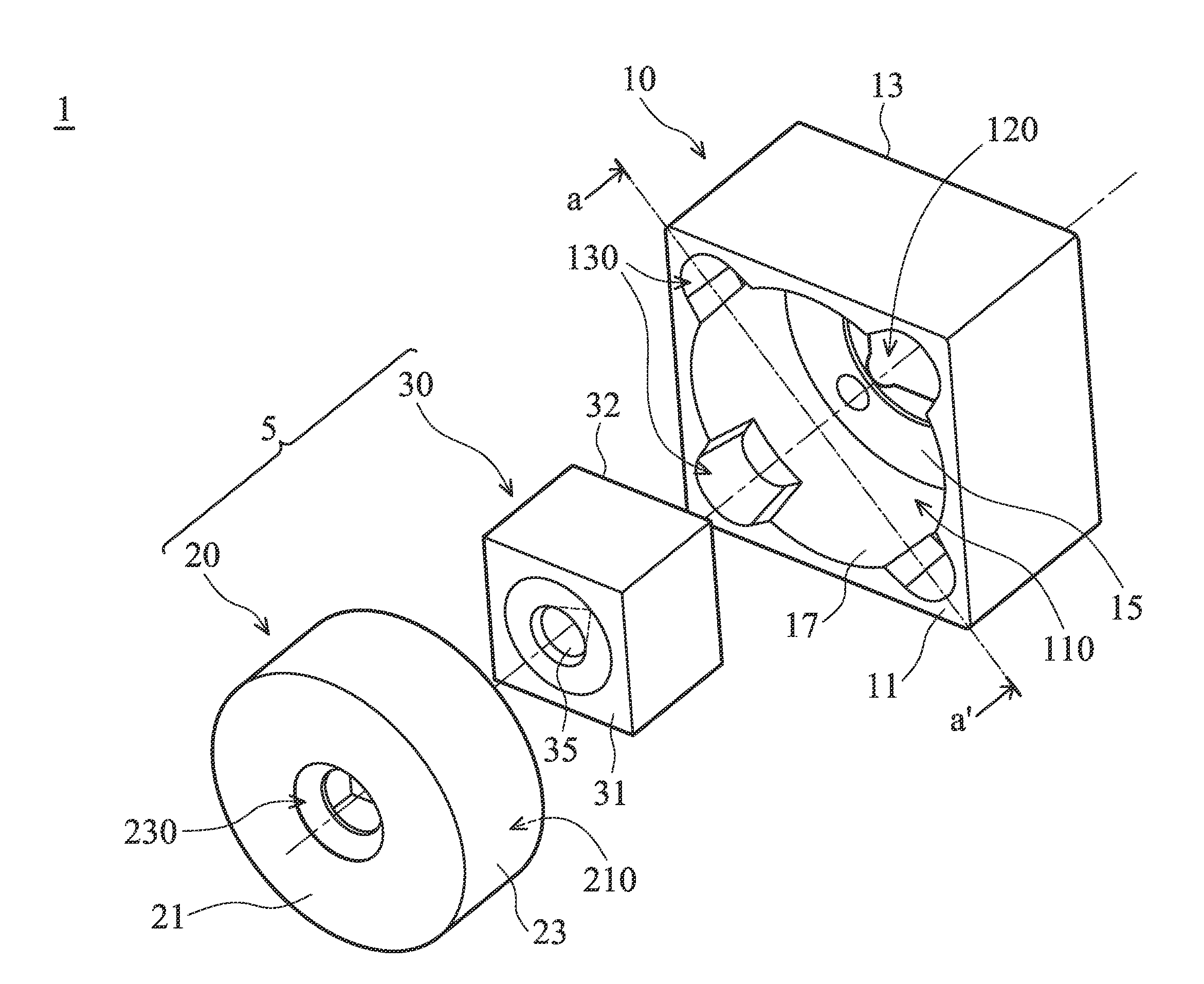
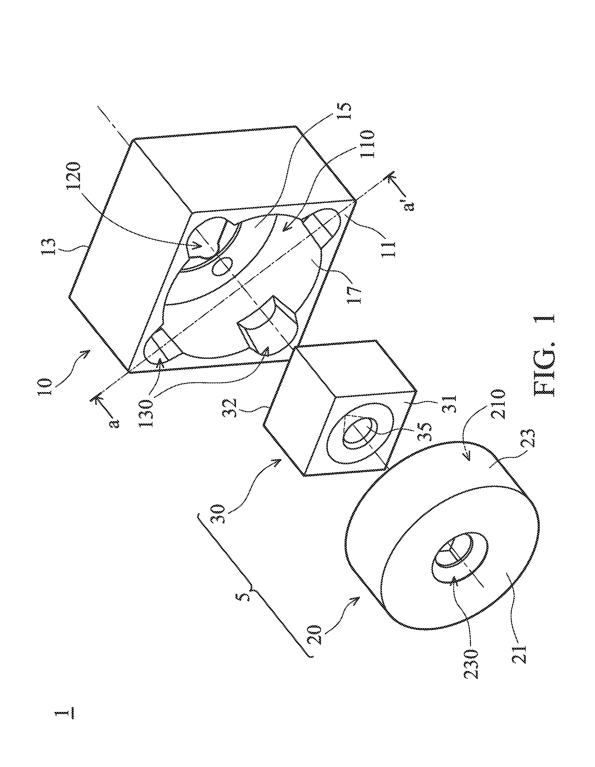
[0026]Referring to FIG. 1, the lens assembly 1 of the disclosure includes a lens barrel 5 and a base 10, and the lens barrel 5 includes a lens holding member 20 and a lens 30 held by the lens holding member 20. While assembly the lens assembly 1, the lens barrel 5 is mounted on the base 10, so that a focal length between the lens barrel 5 and an image sensor (not shown) which is connected to the base 10 is stably maintained.

[0027]The structural features of the lens barrel 5 and the base 10 are described in details. The base 10...


PUM


Abstract

A lens assembly is disclosed, which includes a base and a lens barrel. The base has a front edge, a back edge opposite to the front edge and a passage penetrating the front edge and the back edge. The lens barrel is disposed in the passage and includes a lens and a lens holding member holding the lens, wherein an outer surface of the lens holding member is in contact with an inner wall of the passage, and at least one of the inner wall of the passage and the outer surface of the lens holding member includes a smooth surface, arranged such that a thrust force applied on the lens barrel while assembling the lens assembly causes a sliding movement between the base and the lens barrel on the smooth surface.

Description

BACKGROUND OF THE INVENTION[0001]1. Field of the Invention[0002]The invention relates to an optical element and a method for assembling the same, in particular relates to a lens assembly that is used to capture image and a method for assembling the same.[0003]2. Description of the Related Art[0004]With a progress of technology, various portable electronic products such as mobile phones, personal digital assistants (PDAs), notebook computers, tablet computers, etc. are generally equipped with a micro camera to facilitate users taking pictures in daily life. With a development trend of continuous improvement in performance and declining in price, the camera function has become a basic function of the portable electronic products.[0005]Generally, a micro camera includes an image sensor and a lens assembly. The image sensor may be a charge coupled device (CCD) or a complementary metal-oxide-semiconductor (CMOS) image sensor, etc. The lens assembly may include a lens barrel and a base, w...

Claims


Application Information

Patent Timeline
Patent Type & Authority Applications(United States)
IPC IPC(8): G02B7/02
CPCG02B7/02G02B7/025
Inventor LU, YIN-DONG
Owner HIMAX TECH LTD
Why Eureka
Try Eureka