Surface ambient wrap light fixture

a light fixture and ambient technology, applied in the field of modules of lighting fixtures, can solve the problems of very energy-inefficient light sources of incandescent lights, relatively inefficient leds, and leds can have a significantly longer operational li

Active Publication Date: 2014-09-18
IDEAL IND LIGHTING LLC
View PDF9 Cites 50 Cited by
  • Summary
  • Abstract
  • Description
  • Claims
  • Application Information

AI Technical Summary

Benefits of technology

[0014]An embodiment of a modular light fixture comprises the following elements. A housing subassembly is removably attached to a lighting subassembly. The lighting subassembly comprises at least one light source. Driver electronics are connected to control said at least one light source.

Problems solved by technology

Incandescent lights are very energy-inefficient light sources with approximately ninety percent of the electricity they consume being released as heat rather than light.
Fluorescent light bulbs are more energy efficient than incandescent light bulbs by a factor of about 10, but are still relatively inefficient.
In addition, LEDs can have a significantly longer operational lifetime.
Incandescent light bulbs have relatively short lifetimes, with some having a lifetime in the range of about 750-1000 hours.
Fluorescent bulbs can also have lifetimes longer than incandescent bulbs such as in the range of approximately 10,000-20,000 hours, but provide less desirable color reproduction.
High power LEDs can draw large currents, generating significant amounts of heat that must be managed.
This can present challenges as plenum space decreases in modern structures.
Furthermore, the temperature in the plenum area is often several degrees warmer than the room environment below the ceiling, making it more difficult for the heat to escape into the plenum ambient.

Method used


Image

  • Surface ambient wrap light fixture
  • Surface ambient wrap light fixture
  • Surface ambient wrap light fixture

Examples


Embodiment Construction

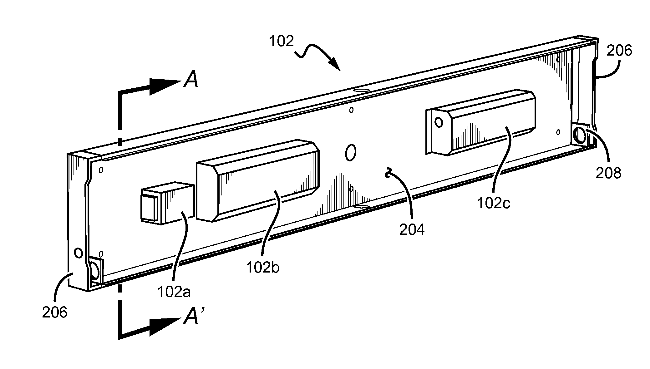
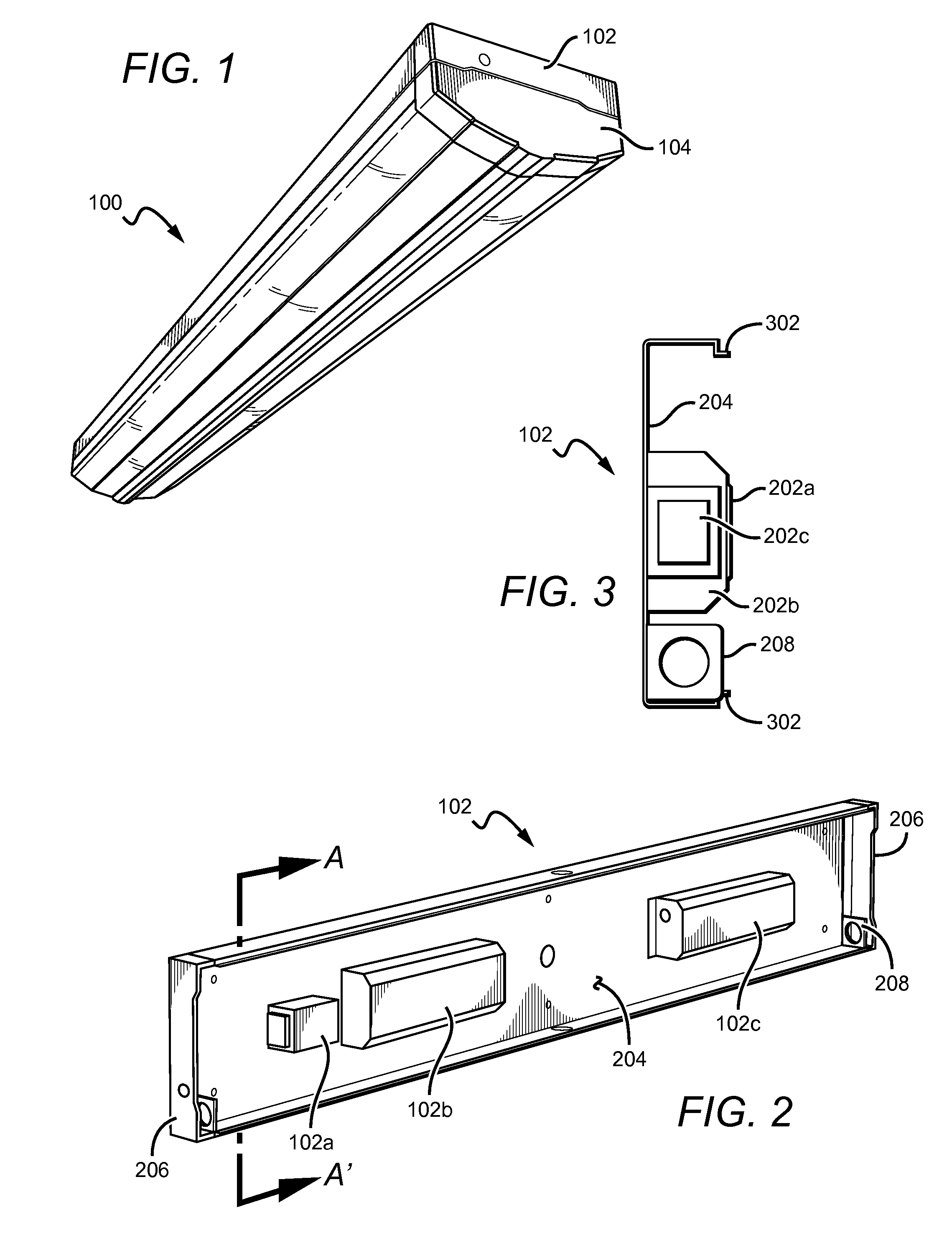
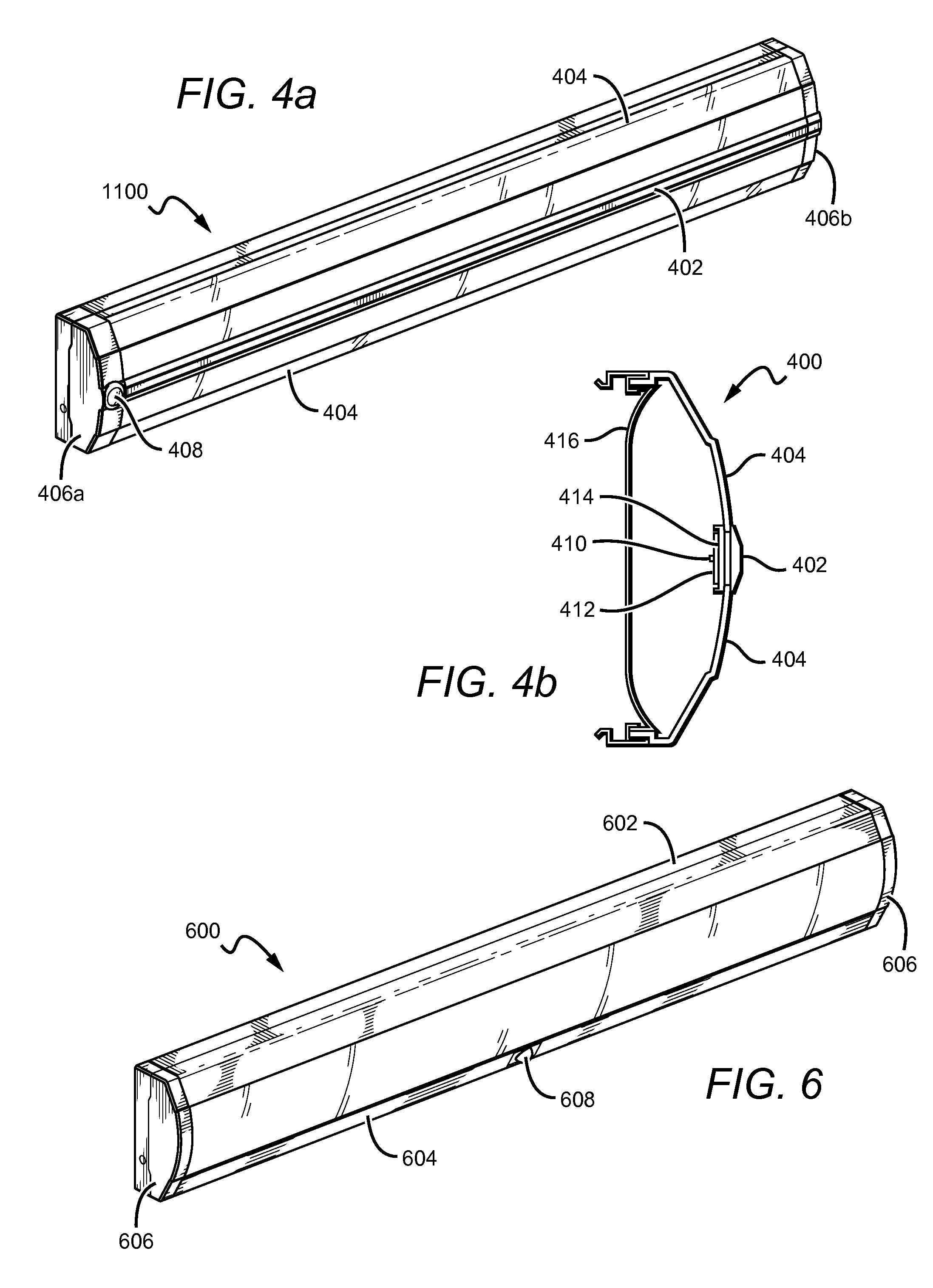
[0052]Embodiments of the present invention provide an indirect modular fixture that is particularly well-suited for use with solid state light sources, such as LEDs, to provide a surface ambient light (SAL). The fixture comprises two structural components: a housing subassembly and a lighting subassembly. These two subassemblies may be removably attached to operate as a singular fixture. Many different lighting subassemblies may be compatible with a single housing subassembly and vice versa. The housing subassembly comprises a frame that is mountable to an external structure. The lighting subassembly comprises the light sources and optical elements that tailor the outgoing light to achieve a particular profile. Both the shape and the arrangement of these elements provide the desired light output distribution. Electronics necessary to power and control the light sources may be disposed in either the housing subassembly or the lighting subassembly. Structural elements, such as end cap...


PUM


Abstract

A modular fixture that is well-suited for use with solid state light sources, such as LEDs, to provide a surface ambient light (SAL). The fixture comprises two structural components: a housing subassembly and a lighting subassembly. These two subassemblies may be removably attached to operate as a singular fixture. Many different lighting subassemblies may be compatible with a single housing subassembly and vice versa. The housing subassembly comprises a frame that is mountable to an external structure. The lighting subassembly comprises the light sources and optical elements that tailor the light to achieve a particular profile. Electronics necessary to power and control the light sources may be disposed in the lighting subassembly. Various mount mechanisms may be used to attach the fixture to a surface such as a ceiling or a wall. Multiple fixtures can be connected serially to provide an extended linear fixture.

Description

RELATED APPLICATIONS[0001]This application is a continuation-in-part of U.S. patent application Ser. No. 13 / 829,558, filed on 14 Mar. 2013, which is incorporated by reference as if fully set forth herein.BACKGROUND OF THE INVENTION[0002]1. Field of the Invention[0003]The invention relates to lighting fixtures and, more particularly, to modular lighting fixtures that are well-suited for use with solid state lighting sources, such as light emitting diodes (LEDs).[0004]2. Description of the Related Art[0005]Troffer-style fixtures (troffers) are ubiquitous in commercial office and industrial spaces throughout the world. In many instances these troffers house elongated fluorescent light bulbs that span the length of the troffer. Troffers may be mounted to or suspended from ceilings or walls. Often the troffer may be recessed into the ceiling, with the back side of the troffer protruding into the plenum area above the ceiling. Typically, elements of the troffer on the back side dissipate ...

Claims


Application Information

Patent Timeline
Patent Type & Authority Applications(United States)
IPC IPC(8): F21V15/01F21V5/04
CPCF21V5/04F21V15/01F21S2/00F21S8/033F21S8/04F21S8/06F21S9/022F21V7/005F21V15/015F21V21/005F21V23/009F21V23/02F21V23/0442F21Y2103/10F21Y2105/10F21Y2105/12F21Y2113/13F21Y2115/10
Inventor LAY, JAMES MICHAELWEST, JENNIFER DENISE
Owner IDEAL IND LIGHTING LLC
Why Eureka
Try Eureka