Turbine Cap for Turbo-Molecular Pump

Active Publication Date: 2014-09-18
TEXAS CAPITOL SEMICON INC
View PDF50 Cites 19 Cited by
  • Summary
  • Abstract
  • Description
  • Claims
  • Application Information

AI Technical Summary

Benefits of technology

[0011]Certain embodiments have the cap member include one or more fins extending from an upper surface thereof. Some example embodiments have the cap member include a channel formed into an upper surface thereof. Some embodiments have cutouts included in

Problems solved by technology

Recently, however, conventional pumps having this design have been found to require increased maintenance due to excessive residual process particulate in the wafer chamber, which can result in lower yields.
This conta

Method used


Image

  • Turbine Cap for Turbo-Molecular Pump
  • Turbine Cap for Turbo-Molecular Pump
  • Turbine Cap for Turbo-Molecular Pump

Examples


Embodiment Construction

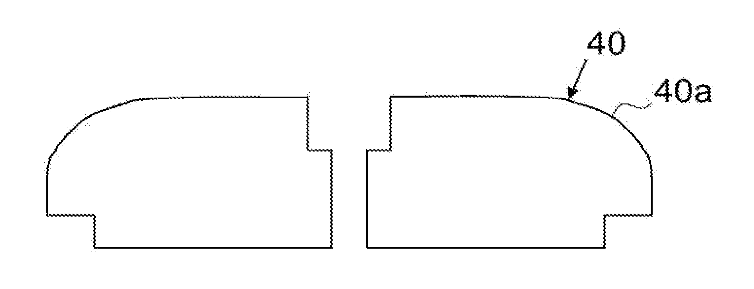
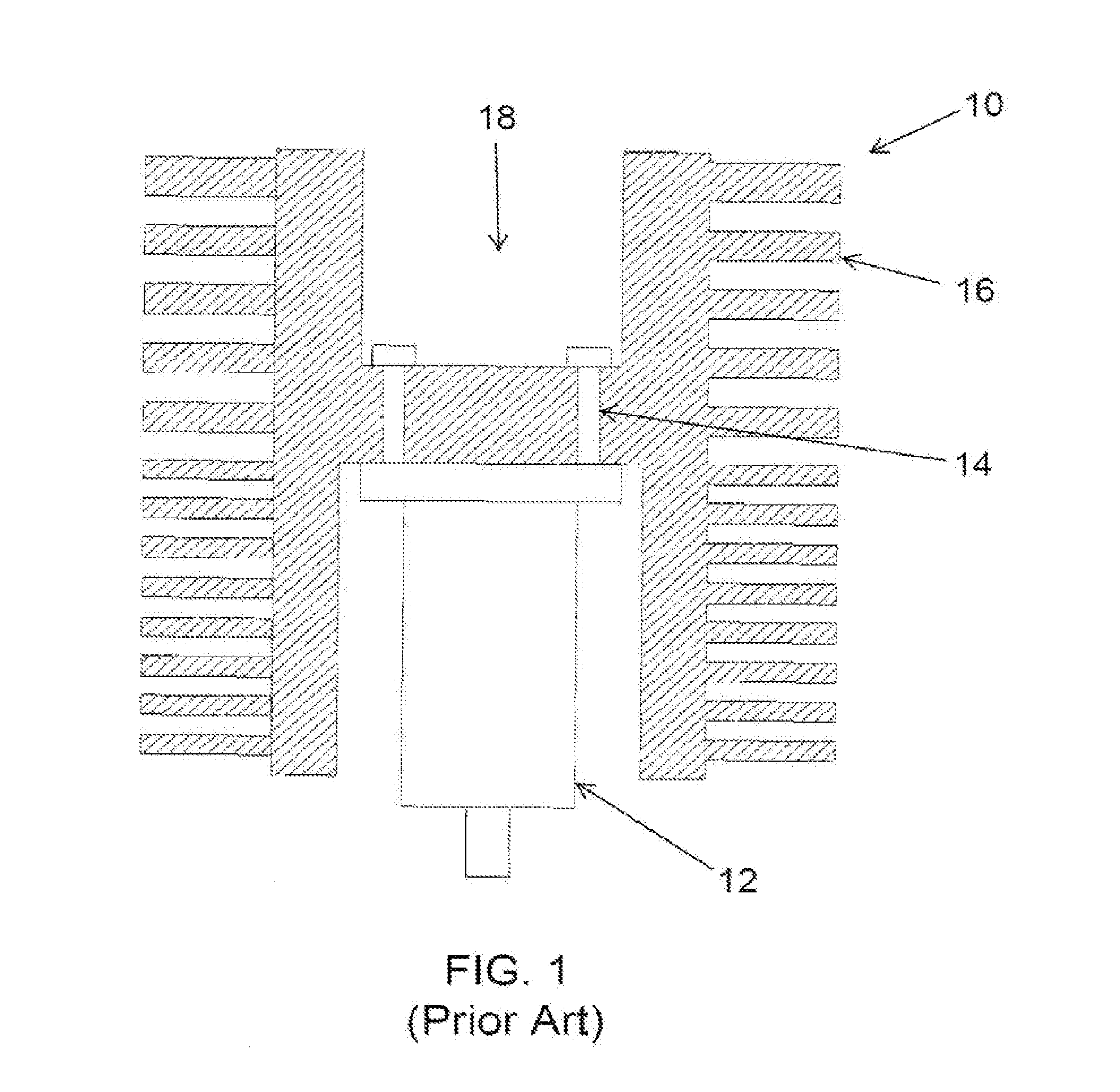
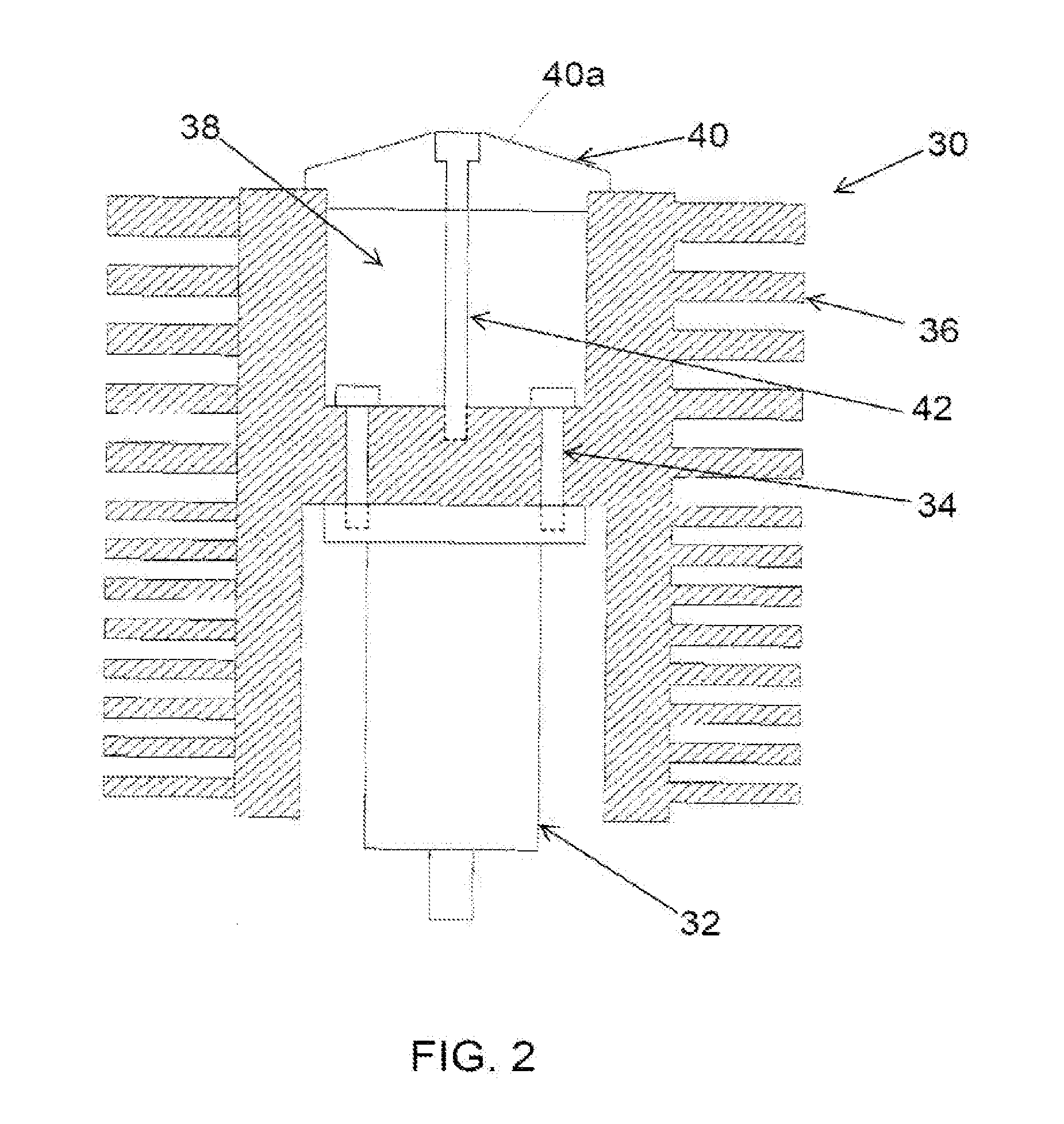
[0027]The present invention is an improved turbine 30 as illustrated in FIG. 2. Turbine 30 is mounted to a pump rotor 32 via mounting bolts 34. The turbine 30 includes fins 36 used to pump the gasses and suspended particles from the chamber (not shown). The tops of the bolts 34 are recessed from the top surface of the turbine 30 in a bolt cavity 38 that has an open end. A cap member 40 is mounted over and seals the open end of the bolt cavity 38. The cap member 40 is mounted to the turbine via a center bolt 42 with sufficient force to form a seal between cap member 40 and turbine 30. The cap member 40 serves two important functions. First, it prevents particles from settling into the bolt cavity 38, where they could later be expelled back into the chamber, and / or preventing any particles in bolt cavity 38 from being expelled out into the chamber. Second, cap 40 has a shaped upper surface 40a which deflects particles away from the center of the turbine and toward the turbine's fins, ...


PUM

PropertyMeasurementUnit
Shapeaaaaaaaaaa
Circumferenceaaaaaaaaaa

Abstract

A turbine assembly mounted to a pump rotor via mounting bolts. The turbine includes fins extending therefrom for pumping gasses and suspended particles from a semiconductor processing chamber. The tops of the bolts are recessed from the top surface of the turbine in a bolt cavity having an open end. A cap member is mounted over and seals the open end of the bolt cavity via a center bolt. The cap member has a shaped upper surface (conical, parabolic, squared, rounded) for deflecting particles away from the center of the turbine and toward the turbine's fins. The cap member's upper surface can include particle deflecting features such as fins, channels or asymmetric shapes to enhance particle deflection as the cap member rotates. The cap member can include a compressible o-ring for a friction fit mounting to the turbine.

Description

RELATED APPLICATIONS[0001]This application claims the benefit of U.S. Provisional Application No. 61 / 783,809 filed 14 Mar. 2013, and which is incorporated herein by reference.FIELD[0002]The present invention relates to turbo-molecular pumps used for semiconductor manufacturing.BACKGROUND[0003]Turbo-molecular pumps are used to draw gasses and suspended particles from chambers that are used to process semiconductor wafers. A conventional pump is illustrated in FIG. 1, and includes a turbine 10 mounted to a pump rotor 12 via mounting bolts 14. The turbine 10 includes fins 16 used to pump the gasses and suspended particles from the chamber (not shown). The tops of the bolts 14 are recessed from the top surface of the turbine 10 in a bolt cavity 18 that has an open end. This conventional design has worked dependably in the past for many years.[0004]Recently, however, conventional pumps having this design have been found to require increased maintenance due to excessive residual process p...

Claims


Application Information

Patent Timeline
IPC IPC(8): F01D25/24
CPCF01D25/243F04D29/321Y10T29/49236F04D19/042F04D29/083
Inventor BOTTOMFIELD, ROGER L.
Owner TEXAS CAPITOL SEMICON INC
Why Eureka
Try Eureka