Dental implant instrumentation and methods

Inactive Publication Date: 2014-09-18
GRANT DENTAL TECH
View PDF7 Cites 5 Cited by
  • Summary
  • Abstract
  • Description
  • Claims
  • Application Information

AI Technical Summary

Benefits of technology

[0008]In another embodiment, the invention provides a drill guide that comprises a drill guide body having a top, a bottom, and an outer periphery. The drill guide body is sized and shaped to be placed into a previously-formed recess in a patient's jawbone. The drill guide body defines a through hole that extends between the top and the bottom. This through hole is configured to receive a drill bit to create a hole in a central portion of the recess

Problems solved by technology

For example, one of the problems with implants is that they must be precisely positioned,

Method used


Image

  • Dental implant instrumentation and methods
  • Dental implant instrumentation and methods
  • Dental implant instrumentation and methods

Examples


Example

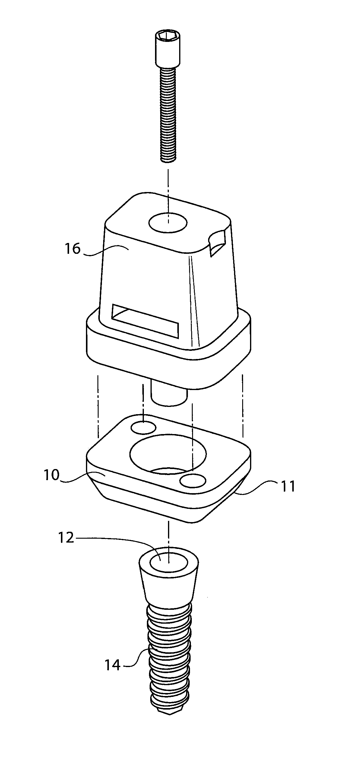
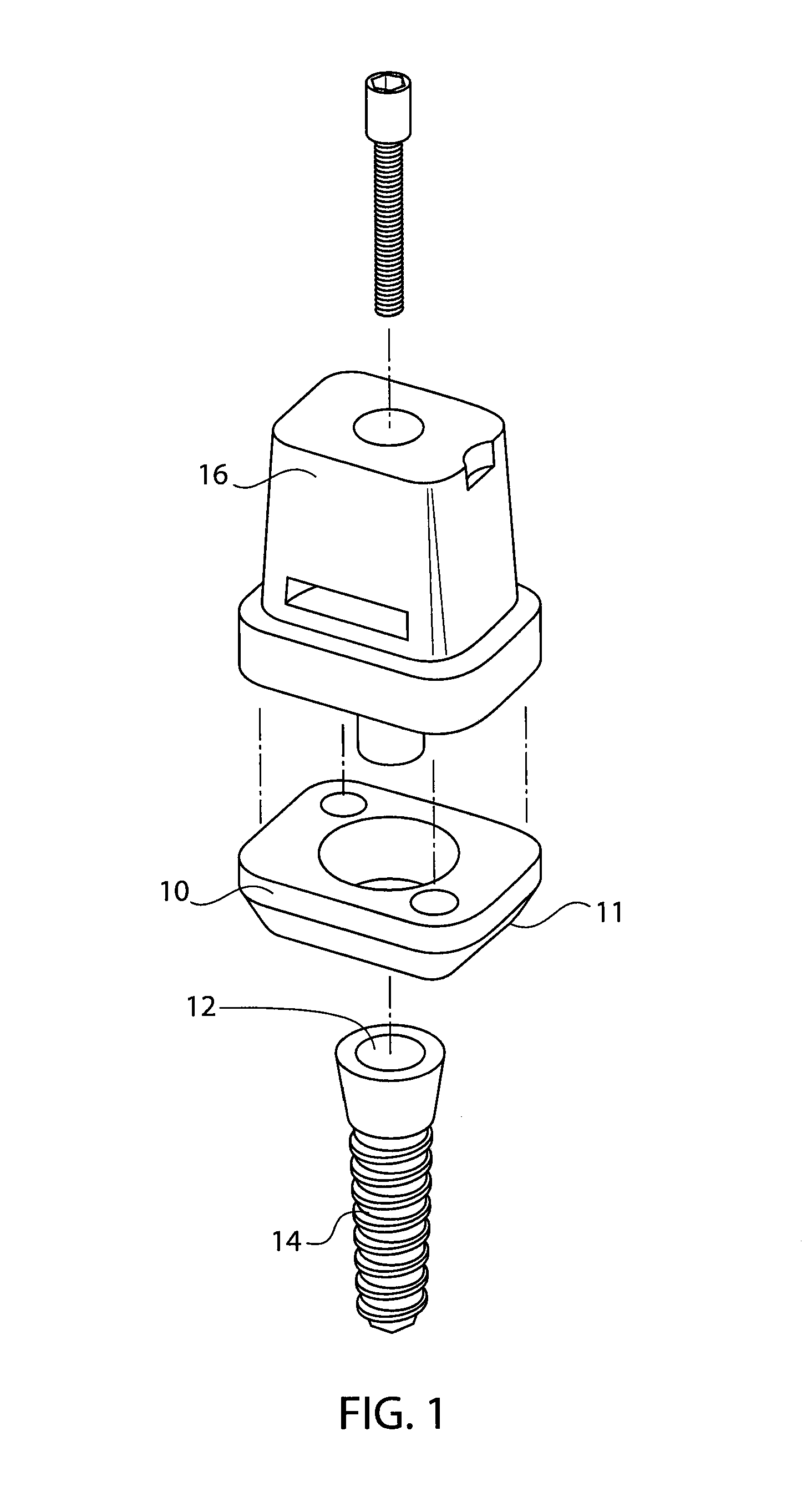
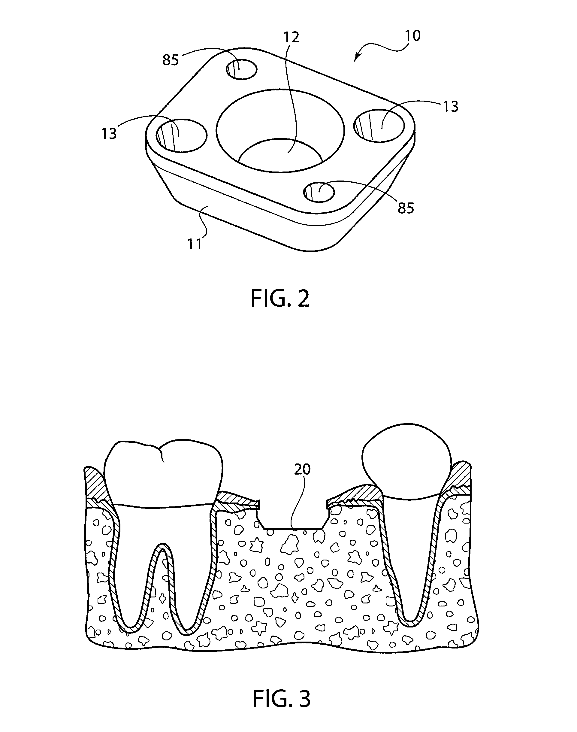
[0032]The instruments described herein are useful for preparing a patient's jawbone to receive an implant of the type described, for example, by U.S. Publication No 2011 / 0151408, the entire contents of which are incorporated herein by reference. Examples of such implants are shown in FIGS. 1-2 and generally include a base platform 10 with a central opening 12, and an implant fastener 14 (such as a screw) that is positioned within the central opening 12 in order to secure the platform 10 to the patient's jawbone. An abutment 16 may be positioned over the base platform 10, and a crown or other tooth restoration element is positioned over the abutment 16.

[0033]In order to position the implant, a section of bone (from a section of the jaw where a tooth is missing) is removed to form a recess 20, as shown in FIG. 3. The recess is formed to have a similar shape and size as the base platform 10 so that only minimal bone growth will be needed in order to fully secure the platform to the bon...


PUM


Abstract

Embodiments of the invention described herein include various instrumentation components designed to install a dental implant. They are provided in order to secure a base platform and to accurately prepare a central opening which receives an implant screw that secures the base platform to the patient's jawbone.

Description

CROSS REFERENCE TO RELATED APPLICATIONS[0001]This application is related to U.S. patent application Ser. No. 13 / 014,526, filed Jan. 26, 2011, U.S. patent application Ser. No. 12 / 694,911, filed Jan. 27, 2010, U.S. patent application Ser. No. 12 / 243,676, filed Oct. 1, 2008, and U.S. patent application Ser. No. 12 / 074,524, filed Mar. 4, 2008, the complete disclosures of which are herein incorporated by reference.FIELD OF THE INVENTION[0002]Embodiments of the present invention relate generally to dental implants, instrumentation for implant surface preparation, as well as methods of use of the implants and instrumentation.BACKGROUND[0003]Implants are becoming a more common way to replace one or more lost teeth. Because they are relatively low maintenance and durable, people tend to prefer implants to bridges. Although technicians have been improving implants and their implantation, further improvements are still needed. For example, one of the problems with implants is that they must be...

Claims


Application Information

Patent Timeline
IPC IPC(8): A61C8/00
CPCA61C8/0089A61C1/084A61C8/0027A61C8/0031
Inventor GRANT, JAMESRENEHAN, BRADLEY WILLIAMSTEWART, DUNCAN
Owner GRANT DENTAL TECH
Why Eureka
Try Eureka