Eureka AIR delivers breakthrough ideas for toughest innovation challenges, trusted by R&D personnel around the world.

Cell chips

a cell chip and array technology, applied in biochemistry apparatus and processes, laboratory glassware, instruments, etc., can solve the problems of difficult washing of cells in wells, no physical intercellular partition of array-based cell chips, and inability to wash cells in wells

Inactive Publication Date: 2014-09-18
SAMSUNG ELECTRO MECHANICS CO LTD +1
View PDF1 Cites 7 Cited by
  • Summary
  • Abstract
  • Description
  • Claims
  • Application Information

AI Technical Summary

Benefits of technology

The present invention aims to provide a cell chip with biomatrices separated from its surface, preventing cross-merging and facilitating washing. Additionally, it intends to adjust the transparency of the substrate and filler to reduce scattering. The invention also includes a substrate with wells that create an environment similar to the human body or animal, ensuring accurate and predictable toxicity data.

Problems solved by technology

However, because the cells are immobilized in the wells, it is difficult to wash the cells in the wells after treating them with medicines.
This problem may in particular become more serious when the size of the wells is reduced and the number of wells is increased in order that more tests can be performed on a single plate, such as 384-well or 1536-well microtiter plate.
However, there is no physical intercellular partition on the array-based cell chip that has been embodied on the flat plate.
Under certain circumstances, this lack of partition allows pharmaceuticals or other test material to undergo cross-merging which can increase the probability of generating a test error and can allow a pharmaceutical that is very small to be exposed to the air and evaporate.
In addition, the plate of the cell chip is often made of a transparent material, and thus may cause scattering when the cells are observed using an optical apparatus such as a CCD or the like.

Method used


Image

  • Cell chips
  • Cell chips
  • Cell chips

Examples


first embodiment

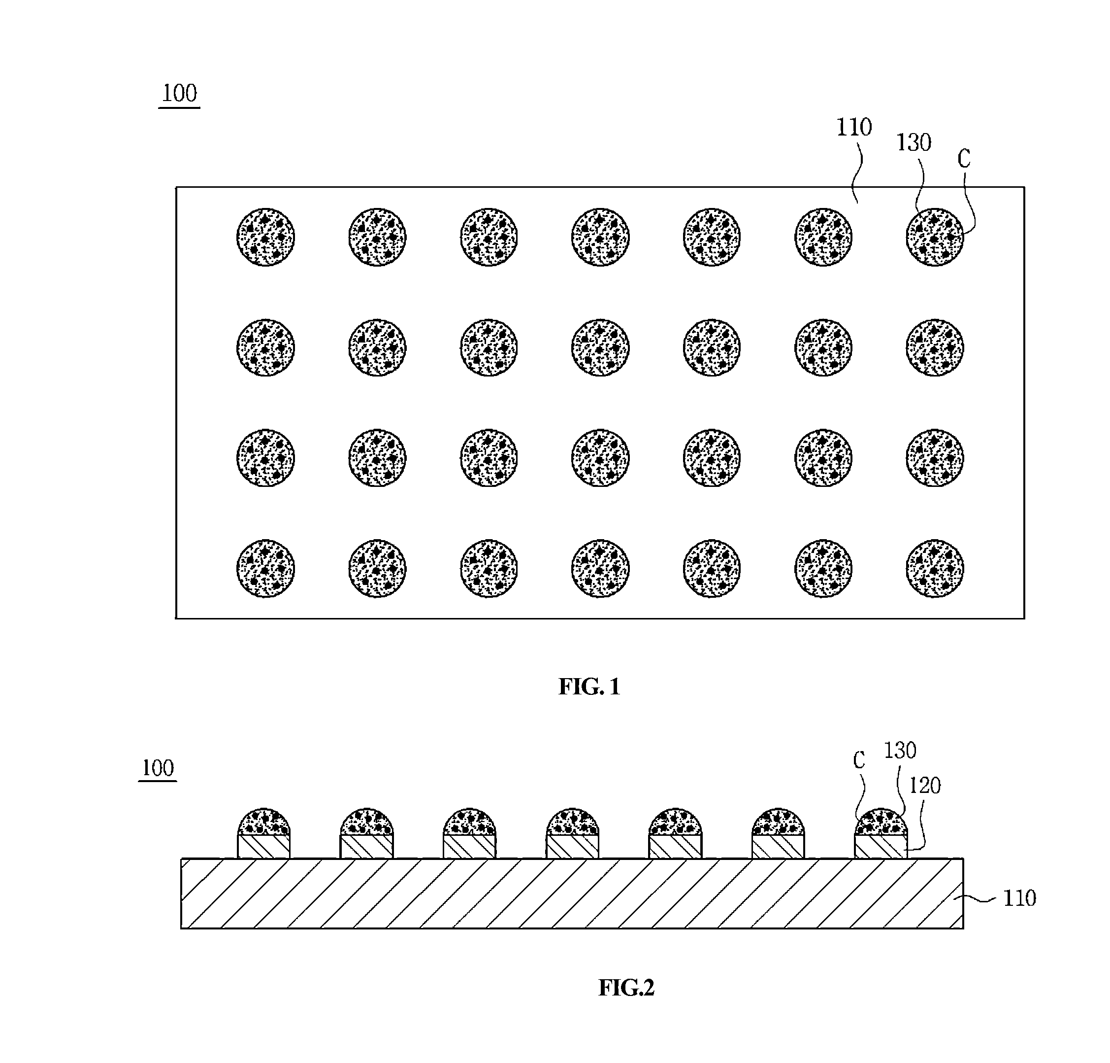
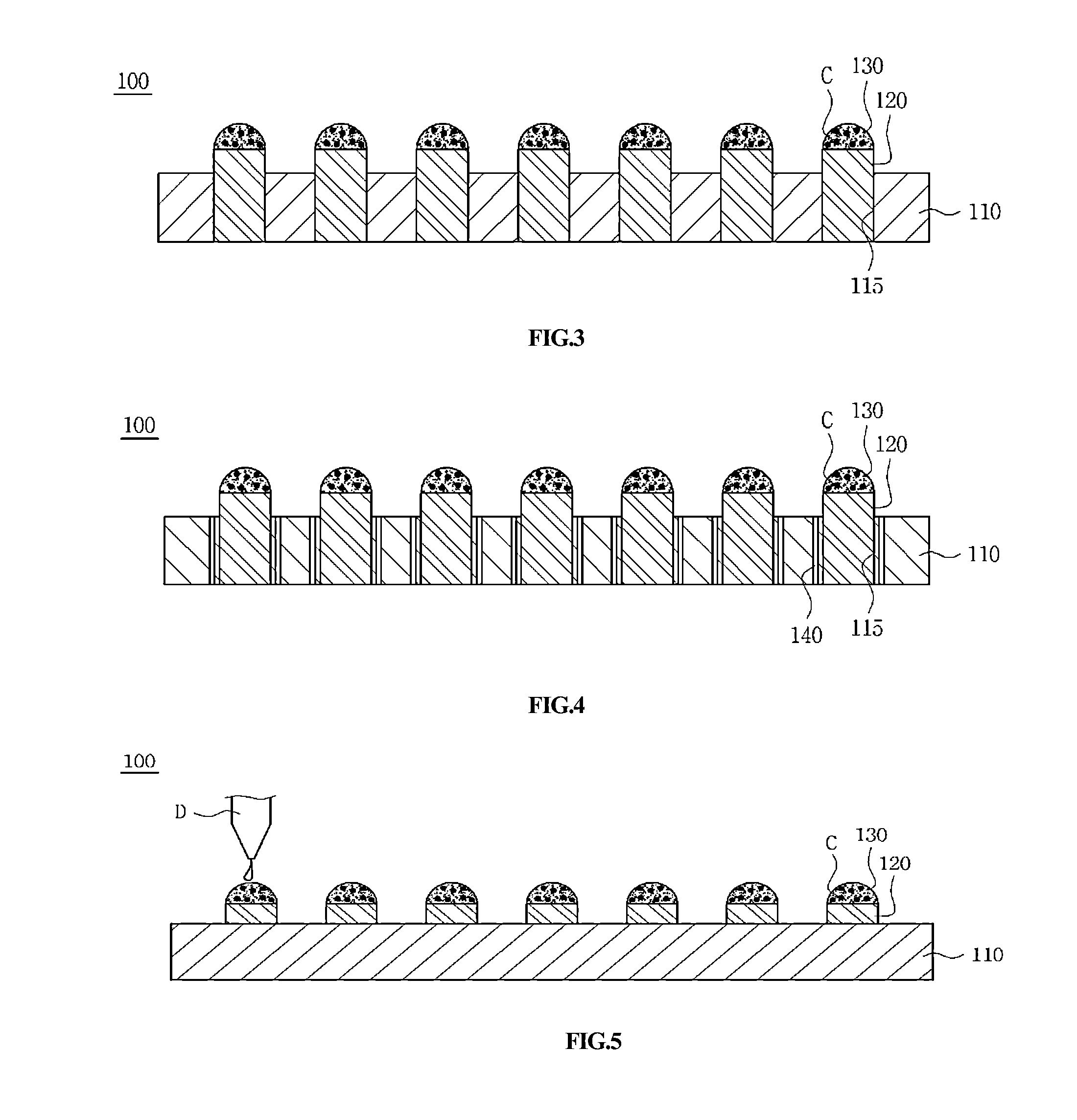
[0040]FIG. 1 is a top plane view schematically showing a cell chip according to the present invention, FIGS. 2 and 3 are a side view and a cross-sectional view schematically showing the cell chip of FIG. 1, FIG. 4 is a cross-sectional view showing a modification of the cell chip of FIG. 3, and FIG. 5 is a side view showing the use of the cell chip of FIG. 1. With reference thereto, the cell chip according to the present invention is described below.

[0041]As shown in FIGS. 1 to 3, the cell chip 100 is configured such that biomatrices 130 for immobilizing a biomaterial C are formed on fillers 120 and the fillers 120 are inserted into the insertion holes 115 of a substrate 110 and protrude from the substrate 110, and thus the biomatrices 130 are separated from the surface of the substrate 110 by a distance.

[0042]The substrate 110 is made of an opaque material. A non-limiting example thereof includes a plastic substrate, a ceramic substrate or the like. Alternatively, the substrate 110 ...

second embodiment

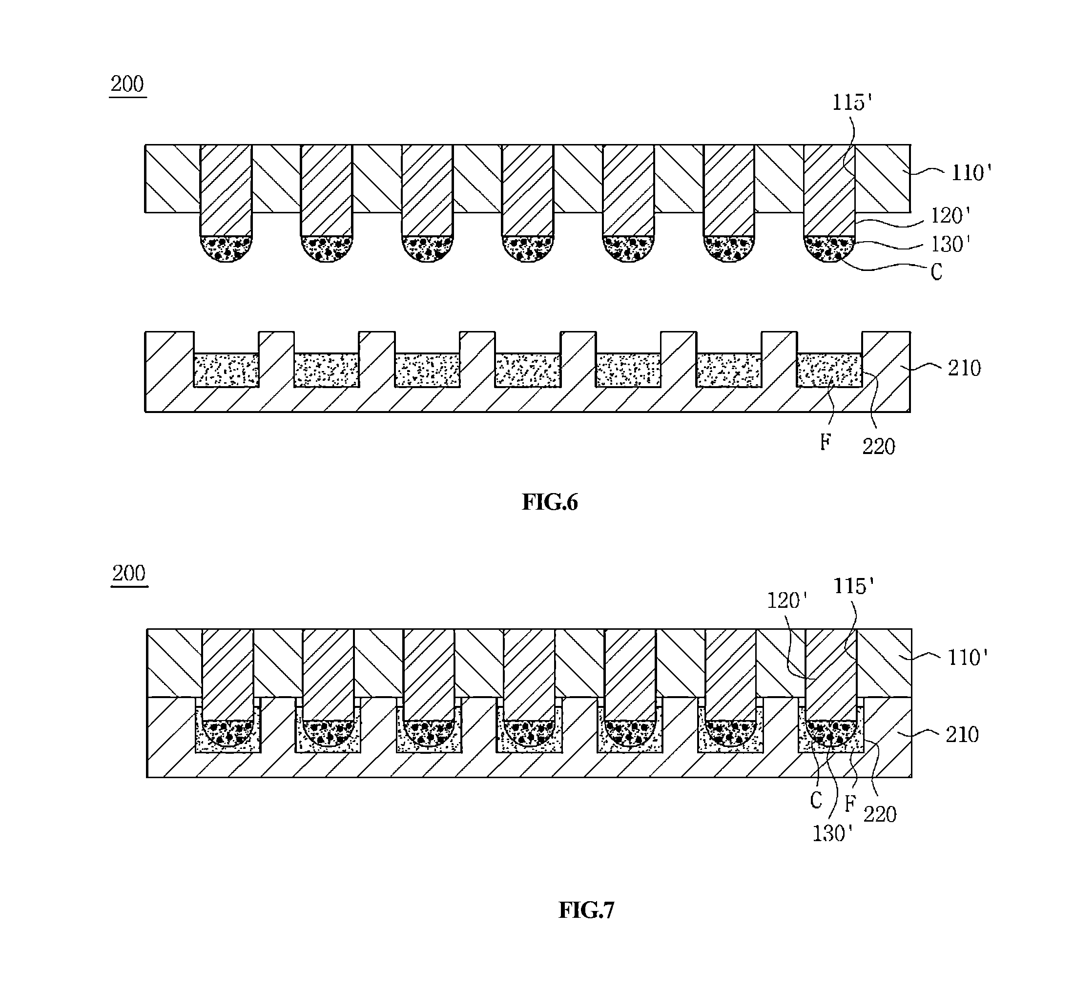
[0062]FIGS. 6 and 7 are cross-sectional views schematically showing a cell chip according to the present invention. With reference thereto, the cell chip according to the present embodiment is described below.

[0063]The cell chip 200 according to the present embodiment further includes a lower substrate 210 having a plurality of wells 220 that store at least one (hereinafter, referred to as a fluid) among a reagent and a culture broth to be supplied to the cell chip as shown in FIGS. 1 to 3. Below, an upper substrate 110′, fillers 120′, and biomatrices 130′ may be configured corresponding to the configuration as described with reference to FIGS. 1 to 3, and thus the detailed description thereof is omitted.

[0064]As shown in FIG. 6, the upper substrate 110′ has a plurality of insertion holes 115′, and the fillers 120′ are inserted into the insertion holes 115′. As such, the fillers 120′ are inserted to protrude from the lower surface of the upper substrate 110′, and the biomatrices 130...


PUM


Abstract

Disclosed is a cell chip and methods for the use thereof, wherein the cell chip includes a substrate made of an opaque material and having a plurality of insertion holes formed therein, a filler made of a transparent material and inserted into each of the insertion holes so as to protrude from the substrate, and a biomatrix which is formed on the filler and immobilizes a biomaterial. Also, another substrate having a plurality of wells which store a fluid is further provided thus forming a 3D cell chip.

Description

RELATED APPLICATION[0001]This application is a continuation of International Application No. PCT / US2012 / 050427, which designated the United States and was filed on Aug. 10, 2012, published in English, which claims the benefit of U.S. Provisional Application No. 61 / 522,747, filed on Aug. 12, 2011. The entire teachings of the above applications are incorporated herein by reference.BACKGROUND OF THE INVENTION[0002]1. Technical Field[0003]The present invention relates to a cell chip.[0004]2. Description of the Related Art[0005]In order to test the toxicity of medicines in vitro, two cell culture methods are typically used One of them is a method of adhering cells to a two-dimensional (2D) surface to culture them (2D cell monolayer culture), and the other is a method of immobilizing cells in a three-dimensional (3D) biomatrix to culture them (3D cell culture). For the 2D cell culture, a microtiter plate (e.g. 6-well, 12-well, 24-well, 96-well, 384-well, 1536-well microtiter plates) compr...

Claims


Application Information

Patent Timeline
IPC IPC(8): G01N33/50
CPCG01N33/5014C12M23/12C12M23/20C12M23/38G01N33/5008B01L3/50853B01L2300/046B01L2300/0636B01L2300/069B01L2300/0819
Inventor LEE, MOO-YEALJEONG, SE HOONKU, BO SUNG
Owner SAMSUNG ELECTRO MECHANICS CO LTD
Why Eureka
Eureka Blog
Learn More