Combination wound and injury treatment apparatus

Active Publication Date: 2014-09-18
FIRST PRINCIPLE INC
View PDF16 Cites 8 Cited by
  • Summary
  • Abstract
  • Description
  • Claims
  • Application Information

AI Technical Summary

Benefits of technology

[0012]In one embodiment, the present disclosure provides a combination wound and injury treatment apparatus that may include thermal packs that may be positioned onto a patient's body part to provide circumferential thermal treatment. A combination wound and injury treatment apparatus in accordance with the disclosure comprises a tubular body having a first opening, a second opening, an inner surface and an outer surface. The first opening, the inner surface and the second opening cooperate to define a passage through the tubular body for the body part. The inner surface of the tubular body may be defined by a continuous flexible material such as, for example, a copolymer of polyes

Problems solved by technology

Rest may be prescribed because continued activity may cause further injury to the body part thereby delaying the healing process, increasing pain, and stimulating internal bleeding.
Although ice may be prescribed to treat injured body parts, ice may cause discomfort when placed between a compressive wrap and an injured body part because it may be a rigid non-conforming solid.
Ice may be also difficult to position on an injured body part, and it tends to melt quickly, which results in a loss of the desired cold treatment and/or frequent disturbance of the injured body part to apply more ice.
Flat packs, while widely used to provide first aid treatment to injured body parts, present certain problems and disadvantages.
One problem with flat packs may be that they do

Method used


Image

  • Combination wound and injury treatment apparatus
  • Combination wound and injury treatment apparatus
  • Combination wound and injury treatment apparatus

Examples


Embodiment Construction

[0024]A detailed description of the hereinafter described embodiments of the disclosed apparatus and method may be presented herein by way of exemplification and not limitation with reference to the Figures.

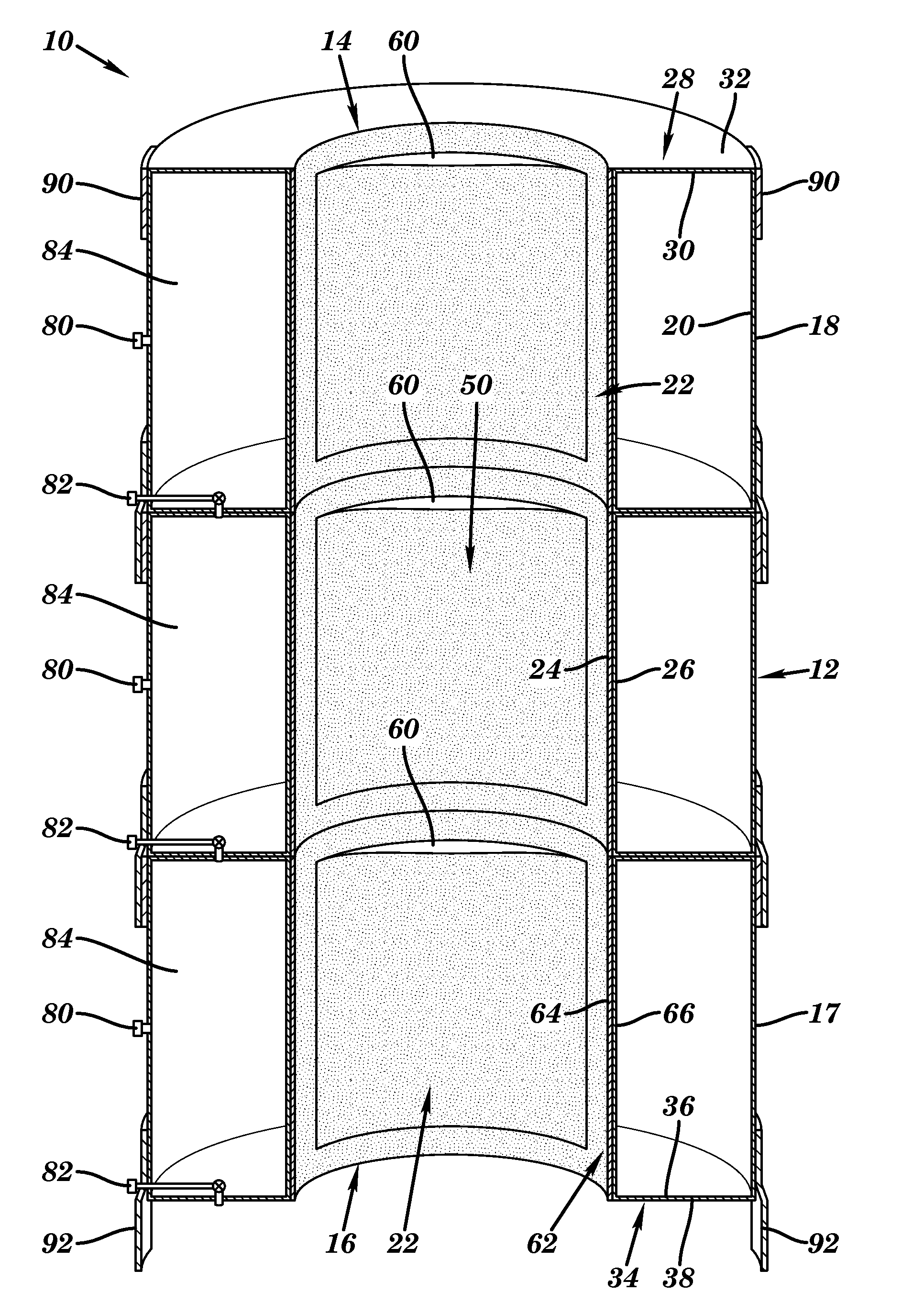
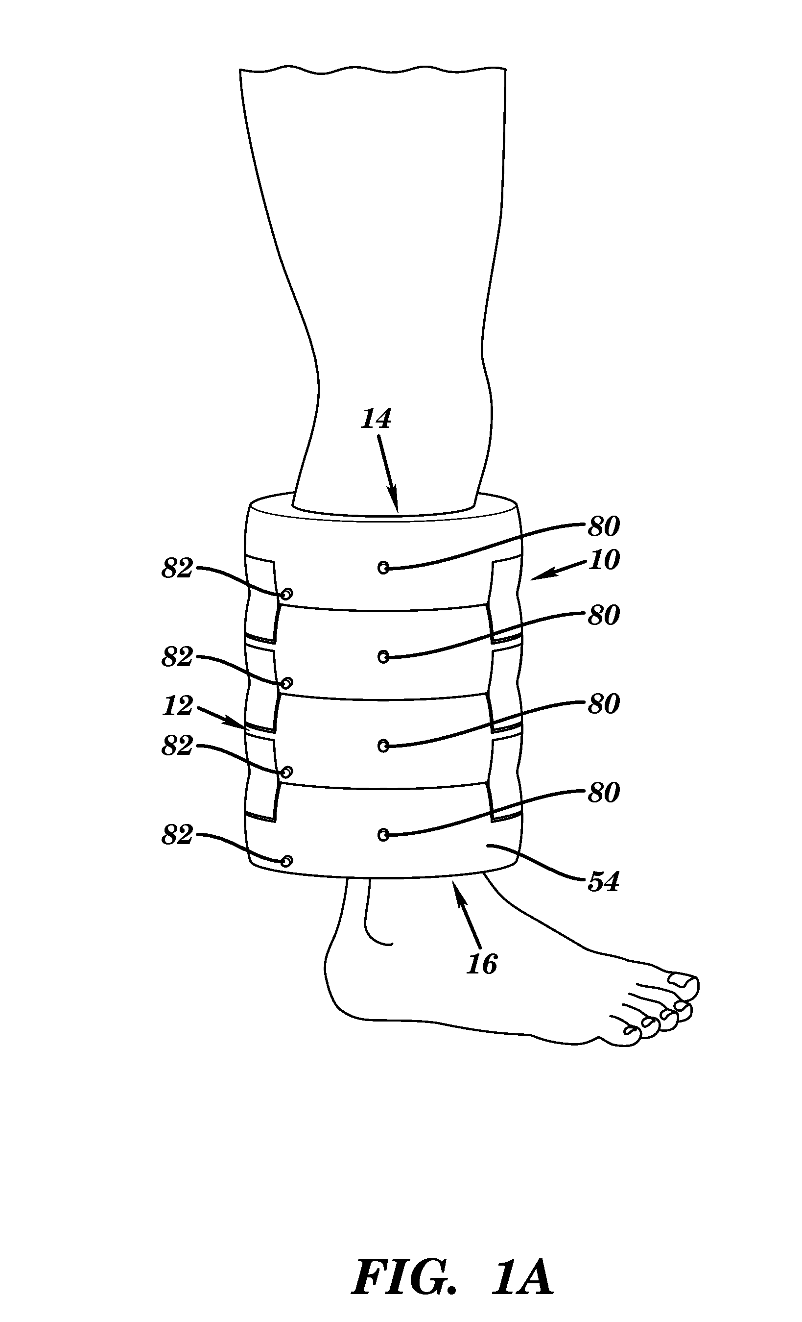
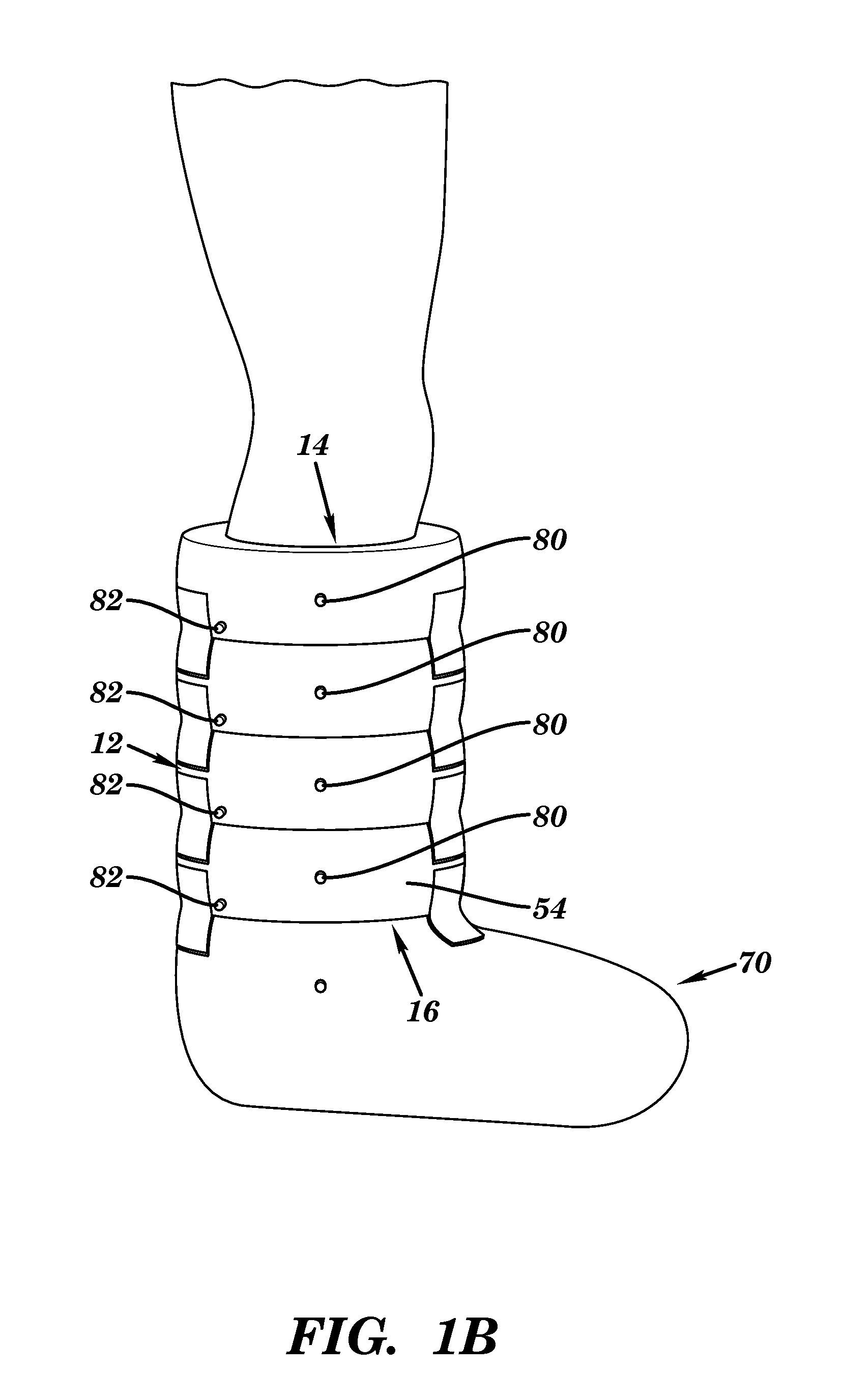
[0025]With reference to FIGS. 1A, 1B and 2, several embodiments of the combination wound and injury treatment apparatus of the present disclosure is illustrated. One embodiment of the combination wound and injury treatment apparatus 10 according to the disclosure may comprise a tubular body 12 having a first opening 14, a second opening 16, an outer wall 17 having in outer surface 18 and an inner surface 20 and an inner wall 22 having an inner surface 24 and in outer surface 26, an upper end member 28 having an inner surface 30 and an outer surface 32 and a lower end member 34 having an inner surface 36 and an outer surface 38, although the disclosure is not limited in this regard. The first opening 14, the inner wall 22 and the second opening 16 may cooperate to define a passage...


PUM


Abstract

Disclosed herein is a combination wound and injury treatment apparatus comprising a tubular body having a first opening, a second opening, a relatively inflexible outer wall having an outer surface and an inner surface. a relatively flexible inner wall having an inner surface and an outer surface, an upper end member having an inner surface and an outer surface and a lower end member having an inner surface and an outer surface, the first opening, the inner surface of the relatively flexible inner wall and the second opening define a passage through the tubular body for receiving a body part; structure formed between the inner surface and the outer surface of the inner wall, the structure being capable of receiving a temperature retaining fluid; a chamber, operatively formed between the inner surface of the outer wall and the outer surface of the inner wall, the chamber being capable of being pressurized; at least one valve, operatively positioned in the outer wall, the at least one valve being capable of regulating the pressure inside the chamber; and a sterile substance, operatively positioned contiguous with the outer surface of the inner wall and being capable of being positioned proximate at least one of a wound and an injury. A combination wound and injury treatment method is also disclosed.

Description

BACKGROUND OF THE DISCLOSURE[0001]The present disclosure is directed to a combination wound and injury treatment apparatus, and more particularly, to a pressurized wound and injury treatment apparatus that may include thermal packs that may be positioned on a patient's body part to provide circumferential thermal treatment at a desired location on the body part and / or pressurized sterile material for the treatment of wounds and / or injuries.[0002]The generally accepted first aid treatment for injuries such as, for example, strains, sprains, contusions, dislocations, uncomplicated fractures and other non-acute injuries to human body parts may be often referred to by the acronym RICE, which stands for rest, ice, compression and elevation. Rest may be prescribed because continued activity may cause further injury to the body part thereby delaying the healing process, increasing pain, and stimulating internal bleeding. Ice may be prescribed because blood vessels contract when exposed to ...

Claims


Application Information

Patent Timeline
IPC IPC(8): A61F5/01A61F7/02
CPCA61F7/02A61F5/012A61F13/00029A61F13/06A61F13/085A61F2007/0043A61F2007/0091A61F2007/0219A61F2007/023A61F2013/00093A61F2013/00174A61F2013/00187A61F2013/00272A61F2013/0028A61F2013/00468A61F2013/00553A61F2013/00574A61F2013/00578
Inventor RANIERE, KEITH A.
Owner FIRST PRINCIPLE INC
Why Eureka
Try Eureka