
Ischemic stroke device

a stroke device and ischemic stroke technology, applied in the field of ischemic stroke devices, can solve the problems of increasing the length of time and complexity of the procedure, the risk of some or all of the obstruction or clot being released into the vasculature of the patient, etc., to reduce the risk of losing, prevent the clot from being scraped off, and reduce the possibility of fragmentation of the obstruction or clot.

Inactive Publication Date: 2014-09-18
DEPUY SYNTHES PROD INC
View PDF12 Cites 110 Cited by
  • Summary
  • Abstract
  • Description
  • Claims
  • Application Information

AI Technical Summary

Benefits of technology

The invention is an apparatus and method for removing a blockage from a blood vessel to treat a medical condition such as a stroke. It helps reduce the risk of losing pieces of the blockage by using an expandable member to cover and secure the blockage before removing it from the patient's body. This close proximity between the expandable members also prevents the blockage from being damage during the procedure. The apparatus includes a telescoping support member to initiate the process of eaving the expandable member. The technical effect of the invention is to provide a safer and more effective way to remove blockages from blood vessels.

Problems solved by technology

However, whenever a captured obstruction or clot is retrieved into any type of catheter there is always a risk of some or all of the obstruction or clot being released into a patient's vasculature.
As the thrombectomy device is pulled back into a catheter, some or all of the obstruction or clot may be scraped off, sending one or more pieces of the obstruction or clot downstream to another artery, after which one or more dislodged pieces of the obstruction or clot will then need to be removed, adding to the length of time and complexity of the procedure.

Method used


Image

  • Ischemic stroke device
  • Ischemic stroke device
  • Ischemic stroke device

Examples


Embodiment Construction

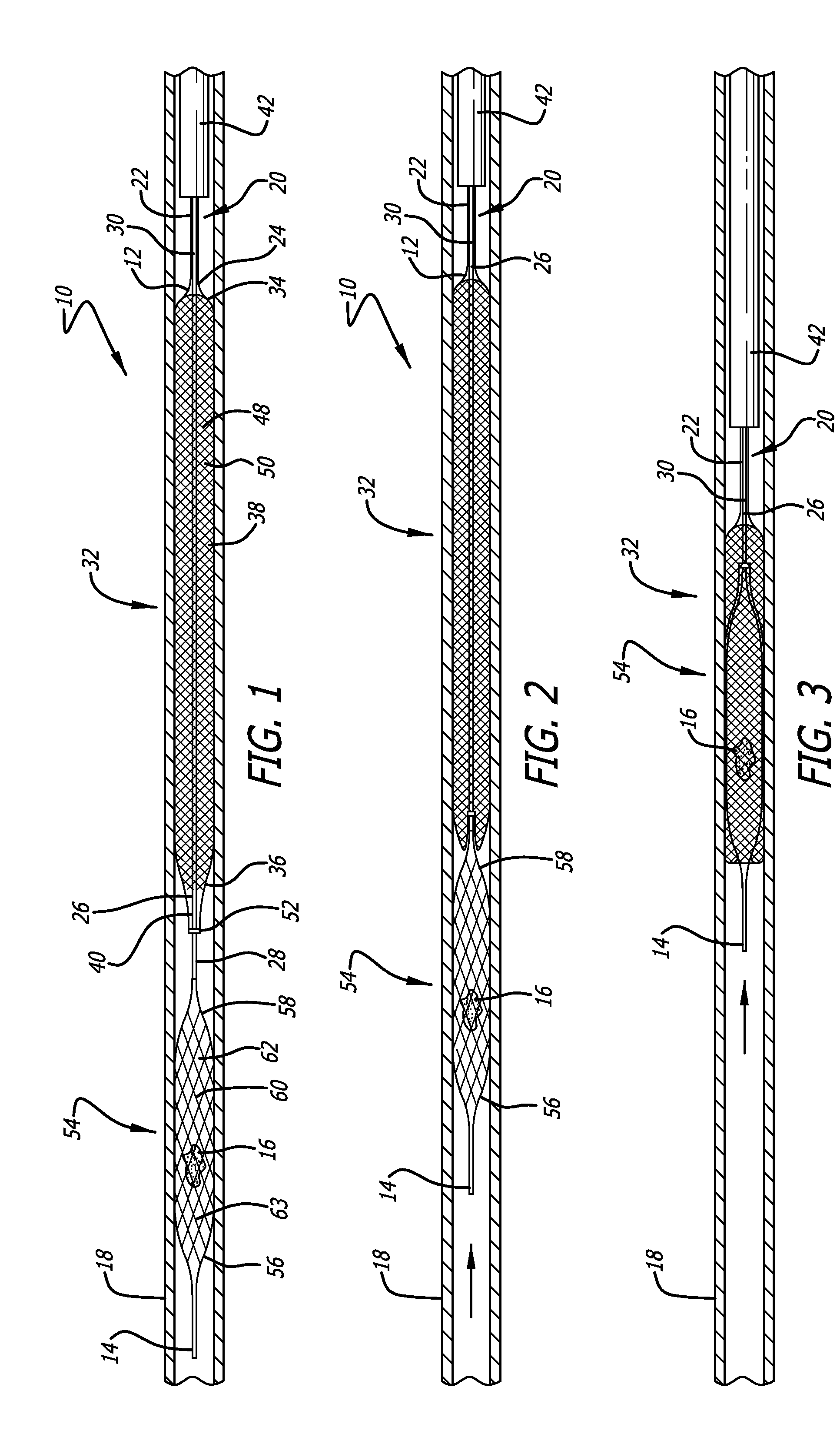
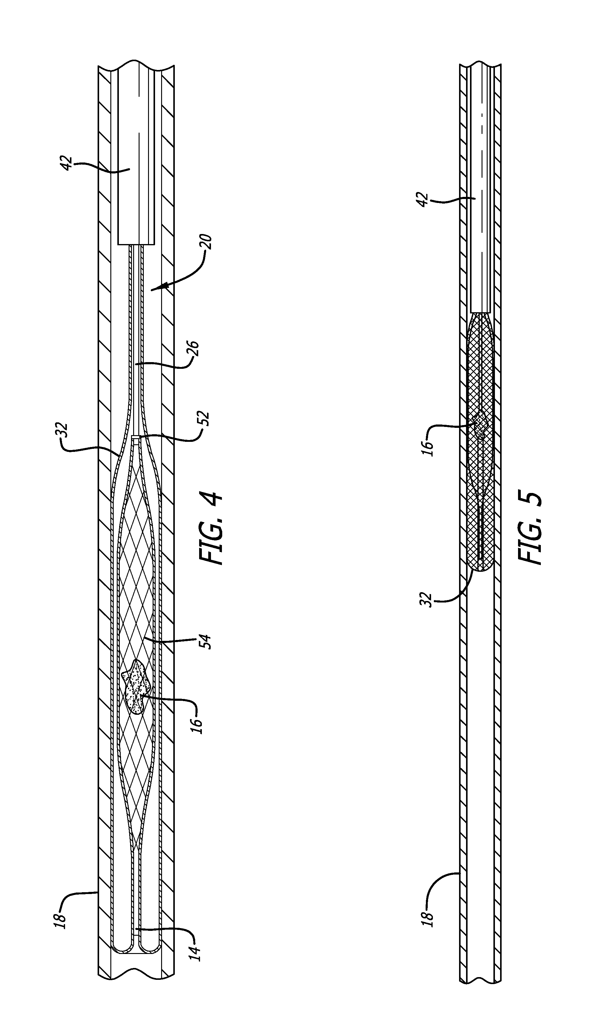
[0022]Referring to the drawings, which are provided by way of example, and not by way of limitation, the present invention provides for an apparatus 10 having a proximal end 12 and a distal end 14, for removal of at least a portion of an obstruction 16, such as a clot, for example, from an obstructed blood vessel in a patient's vasculature 18, such as for treatment of ischemic stroke, for example.

[0023]The apparatus includes a telescoping support member 20, including an outer tubular shaft 22 having a distal end 24, and an inner elongate member or core advancement wire 26 having a distal end 28 and a proximal portion 30, and extending through the outer tubular shaft and slidable within the outer tubular shaft. The apparatus also includes a first, proximal expandable member or cover element 32 having a proximal end 34 and a distal end 36, and a tubular body 38 extending between the proximal and distal ends of the first or proximal expandable member. The proximal end of the first or p...


PUM


Abstract

An ischemic stroke device includes a telescoping support member, a first or proximal expandable member connected to the telescoping support member, and a second or distal expandable member connected to the first expandable member. A proximal portion of the first expandable member is attached to a distal end of an outer shaft of the telescoping support member, and a distal end of the first expandable member is attached to a distal portion of an inner core wire of the telescoping support member. The proximal end of the second expandable member is permanently joined to the distal end of the inner core wire. The first expandable member everts to cover the second expandable member that is used to capture an obstruction or clot, prior to pulling the obstruction or clot into a catheter for removal from a patient's vasculature.

Description

BACKGROUND OF THE INVENTION[0001]The present invention relates to an apparatus and method for increasing blood flow through an obstructed blood vessel and, more particularly relates to an apparatus and method for removal of at least a portion of an obstruction such as a clot from an obstructed blood vessel for treatment of ischemic stroke.[0002]A common treatment for ischemic stroke is the use of a thrombectomy device to physically remove an obstruction such as a blood clot from the affected artery. One such thrombectomy device typically is advanced through a microcatheter into the vasculature, and is deployed into an obstruction or clot in the vasculature by pulling back on the microcatheter, allowing the thrombectomy device to capture at least a portion of the obstruction or clot, and the thrombectomy device is then retrieved by withdrawing the thrombectomy device into a catheter such as a guide catheter or an intermediate catheter. To prevent the loss of the captured portion of t...

Claims


Application Information

Patent Timeline
Patent Type & Authority Applications(United States)
IPC IPC(8): A61B17/22A61M25/10
CPCA61B2017/00991A61B17/221A61M25/10A61B17/22032A61B2017/22051A61B2017/22084A61B2017/2212
Inventor FOLLMER, BRETT ALLENASUNCION, SHEILA VALLESTEROS
Owner DEPUY SYNTHES PROD INC
Learn More