Anastomotic device and method

a technology of anastomosis and anastomosis, which is applied in the field of surgical devices and methods, can solve the problems of time-consuming process, incongruity, and human error

Inactive Publication Date: 2014-09-18
TC1 LLC
View PDF7 Cites 9 Cited by
  • Summary
  • Abstract
  • Description
  • Claims
  • Application Information

AI Technical Summary

Benefits of technology

[0006]In summary, one aspect of the present invention is directed to an anastomotic system including a plurality of needles loaded with sutures and a delivery tool. The sutures include a suture core and crimp or fastener

Problems solved by technology

This is a time consuming process that is also open to the p

Method used


Image

  • Anastomotic device and method
  • Anastomotic device and method
  • Anastomotic device and method

Examples


second embodiment

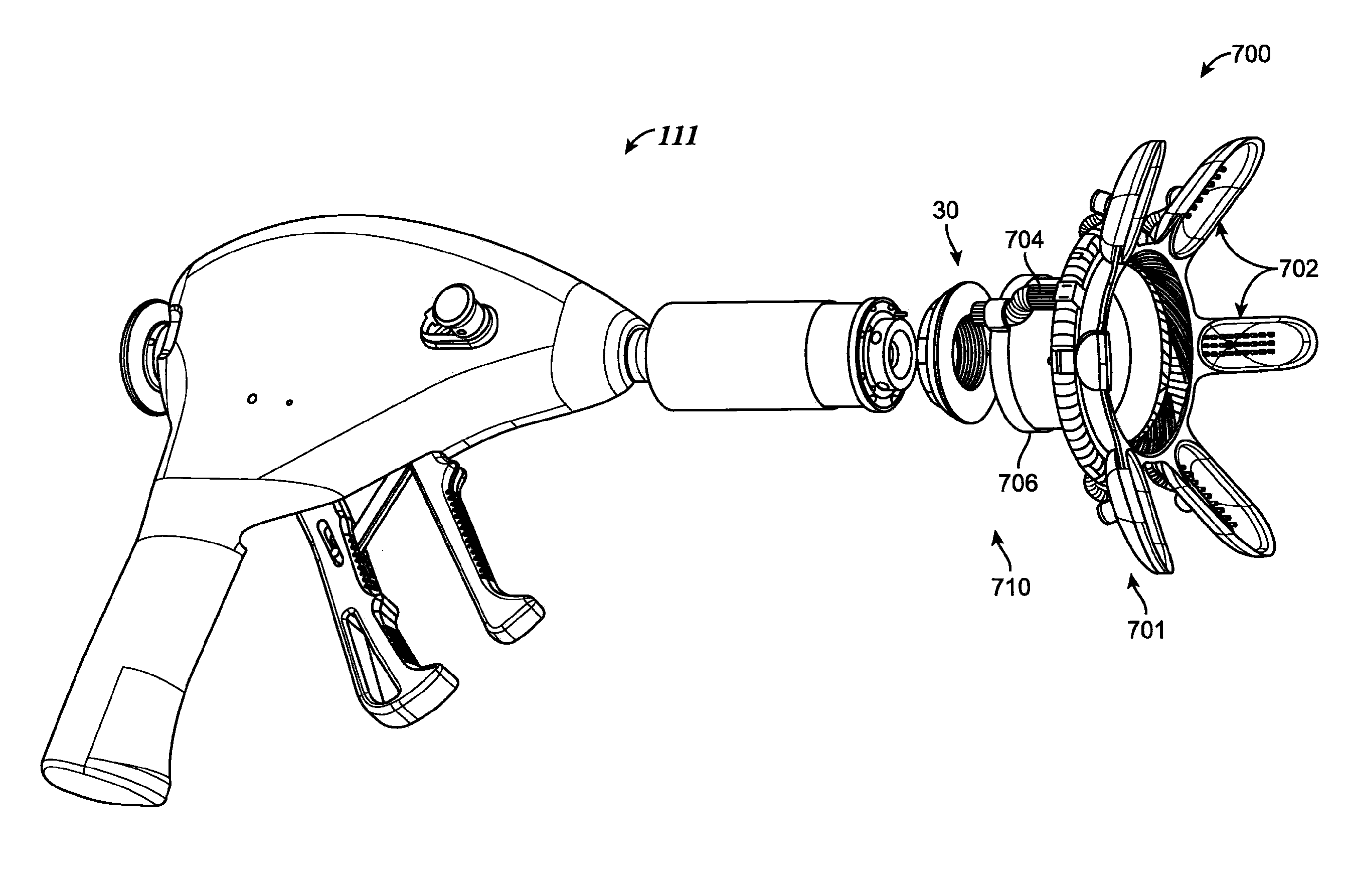
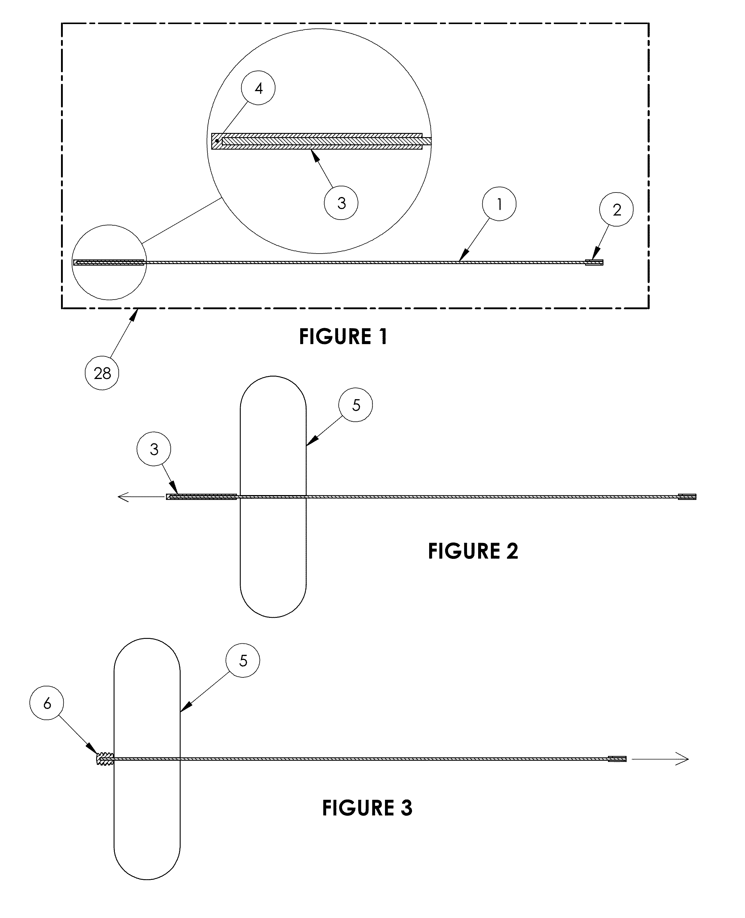
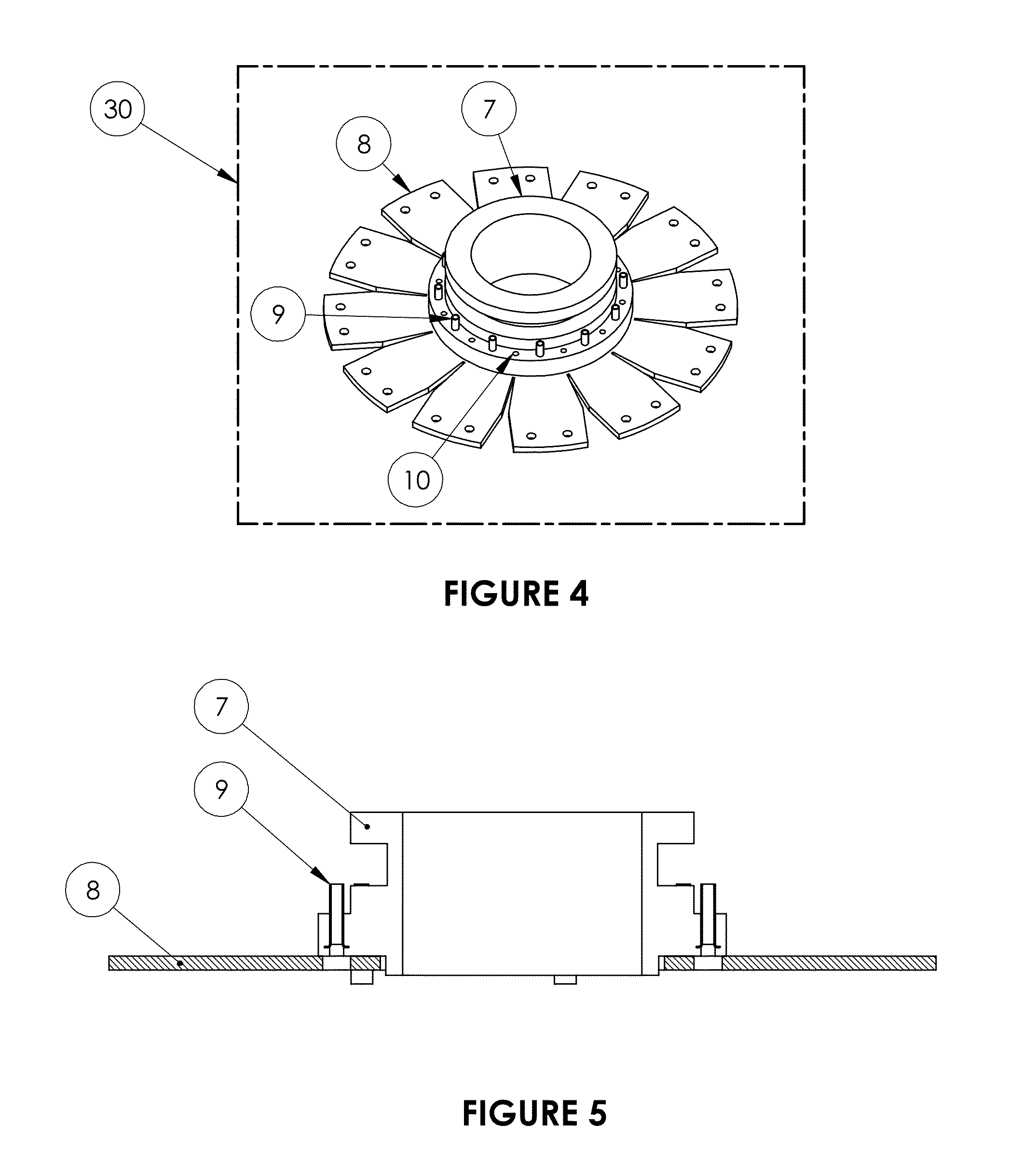
[0074]A second embodiment of a delivery tool is described below in connection with FIGS. 20-36. This embodiment shows delivery tool 111 which is similar to delivery tool 29, except that delivery tool 111 is operated through the use of hand actuated levers which drive and retract a needle (also called a “clip”), instead of using air pressure. Although delivery tool 111 is described in connection with a solid (not hollow) needle or clip 136, it is to be understood that delivery tool 111 can be adapted to carry attachment ring 30 of FIGS. 4 and 5 and suture device 28 of FIG. 1 and adapted to cinch suture device 28 to secure attachment ring 30 onto tissue. In such an adaptation, needle 24 may be modified to include catch 46 (FIG. 28) to allow delivery tool 111 to push needle 24 out of delivery tool 111 and into tissue. Delivery tool 111 pulls crimp 2 of suture device 28 during a cinching process. Hollow needle 24 of FIGS. 9 and 14-16, when in its natural, unconstrained state, can have t...

third embodiment

[0113]A third embodiment of a delivery tool is described below in connection with FIGS. 37A-37E. This embodiment shows delivery tool 211 which is similar to delivery tool 29, except that delivery tool 211 is operated through the use of movable grip 16 and handle 18 to drive and retract a needle (also referred to as a clip), instead of using air pressure. Although delivery tool 211 is described below in connection with a solid (not hollow) clip 136, it is to be understood that delivery tool 211 can be adapted to carry attachment ring 30 of FIGS. 4 and 5 and suture device 28 of FIG. 1 and adapted to cinch suture device 28 to secure attachment ring 30 onto tissue. In such an adaptation, needle 24 may be modified to include catch 46 (FIG. 28) to allow delivery tool 211 to push needle 24 out of delivery tool 211 and into tissue. Delivery tool 211 pulls crimp 2 of suture device 28 during a cinching process.

[0114]FIG. 37A shows delivery tool 211 for anchoring attachment ring 30 to biologic...


PUM


Abstract

An anastomotic system including a plurality of needles loaded with sutures and a delivery tool. The sutures include a suture core and crimp or fastener member at a proximal end of the core. An anchoring sleeve is optionally provided at a distal end. The anchoring sleeve is configured to collapse and prevent retraction of the suture after insertion through the tissue wall. A method of deploying the needles using the delivery tool is also disclosed.

Description

CROSS REFERENCE TO RELATED APPLICATIONS[0001]This application claims the benefit of U.S. Provisional Application No. 61 / 799,877, filed Mar. 15, 2013, the entire disclosure of which is incorporated herein for all purposes by reference.INCORPORATION BY REFERENCE[0002]All publications and patent applications mentioned in this specification are herein incorporated by reference to the same extent as if each individual publication or patent application was specifically and individually indicated to be incorporated by reference.FIELD[0003]This invention relates, in general, to a surgical device and method, and more particularly to anastomotic tools and methods for their use.BACKGROUND[0004]Mechanical circulatory support has increasingly become a standard of care for advanced heart failure. An example of a circulatory support system is a left ventricle assist device (LVAD) for pumping blood from the heart to the ascending aorta. The LVAD is typically implanted at the apex of the left ventri...

Claims


Application Information

Patent Timeline
IPC IPC(8): A61B17/11A61B17/04
CPCA61B17/11A61B17/0469A61B17/06166A61B17/30A61B19/5202A61B2017/00243A61B2017/1135A61B2017/00867A61B2017/0417A61B2017/0472A61B2017/06052A61B2017/06171A61B2017/1107A61B2017/00544A61B90/30A61B2017/06095A61B2017/308
Inventor HOARAU, CARINEREICHENBACH, STEVEN H.HSU, GEORGEJACOBS, ROBERT A.
Owner TC1 LLC
Why Eureka
Try Eureka