Innovative Approach to Distributed Energy Resource Scheduling

a distributed energy resource and scheduling technology, applied in the field of power systems, can solve the problems of increasing the cost of upgrades, and increasing the cost of bulk generation schemes, so as to achieve the effect of keeping operating costs low

Active Publication Date: 2014-09-18
ORACLE INT CORP
View PDF31 Cites 192 Cited by
  • Summary
  • Abstract
  • Description
  • Claims
  • Application Information

AI Technical Summary

Benefits of technology

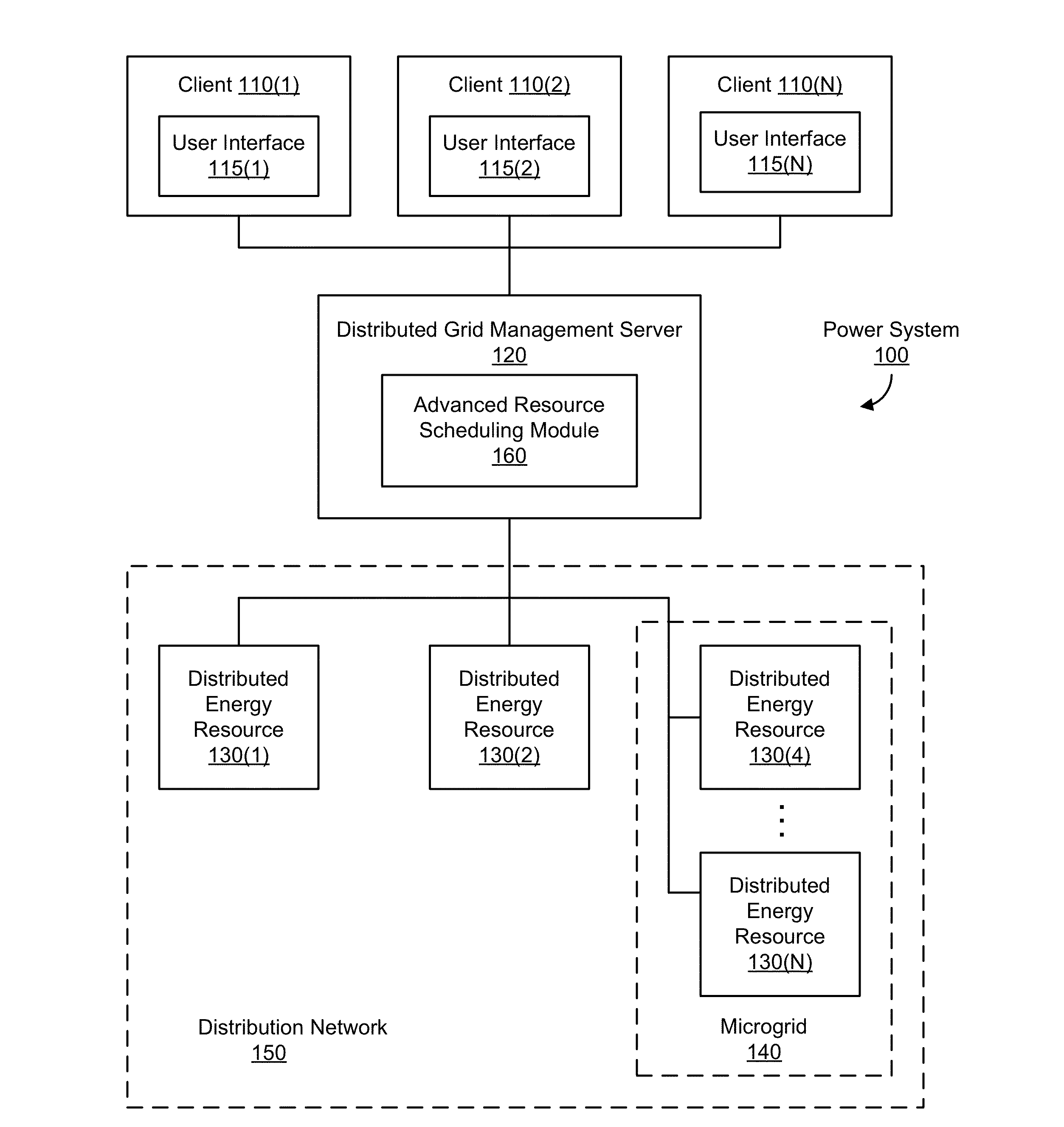
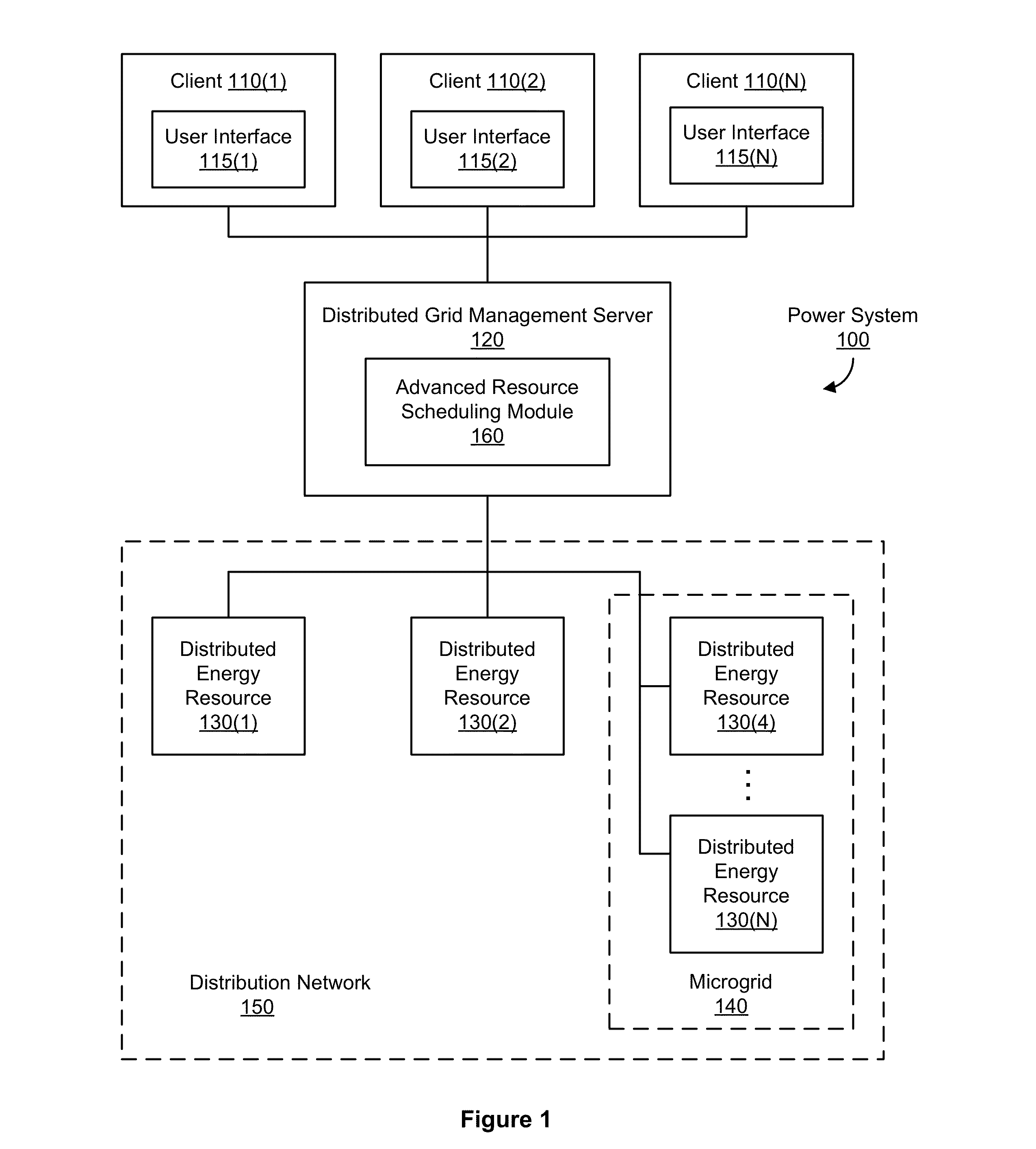
[0005]The present disclosure provides for distributed resource scheduling performed by an advanced resource scheduling (ARS) module implemented on a distributed grid management (DGM) server in a power system. Customers place a power demand or required load on a distribution network of a power system for a certain amount of power (e.g., electrical power or electricity). Distributed energy resources (DERs) are configured to provide, in aggregate, enough power output to meet or satisfy the power demand. Each DER is configured to perform its energy function (e.g., generating power or storing the generated power as energy that can be later provided to the distribution network) at some operating cost (e.g., cost of fuel to perform its energy delivery function). Thus, a combination of DERs is desired to b...

Problems solved by technology

Meeting energy (or power) demands of customers in a cost-effective way is an age-old problem in the energy utility industry.
As customers' power demands have evolved and existing systems have aged, additional pressures have been placed on such a traditional bulk generation scheme.
Such upgrades can be quite expensive.
For example, the costs involved in power generation at a first energy source may be more expensive than at a second energy source, and thus the first energy source may be scheduled to generate a limited amount of power in order to save costs.
Optimal sc...

Method used


Image

  • Innovative Approach to Distributed Energy Resource Scheduling
  • Innovative Approach to Distributed Energy Resource Scheduling
  • Innovative Approach to Distributed Energy Resource Scheduling

Examples


example software implementation

[0174]FIG. 9 illustrates an example class hierarchy for an example software implementation of a particle swarm optimization algorithm. In the embodiment illustrated, class PSOInstance 905 includes various methods, such as an initialize( ) method and a solve( ) method, discussed below. ARS module can generate (or instantiate) an object of class PSOInstance 905 for each distributed resource scheduling problem that ARS module is solving. PSOInstance class 905 includes a swarm class 910, where a PSOInstance object (e.g., an instantiated object of PSOInstance class 905) can include multiple swarm objects (e.g., multiple instantiated objects of swarm class 910). Swarm class 910 includes particle class 915, where a swarm object can include multiple particle objects. Particle class 915 also includes various functions that are discussed below. Particle class 915 also includes FitnessFunction class 935, which provides functions used to evaluate fitness of a swarm object (where the swarm objec...


PUM


Abstract

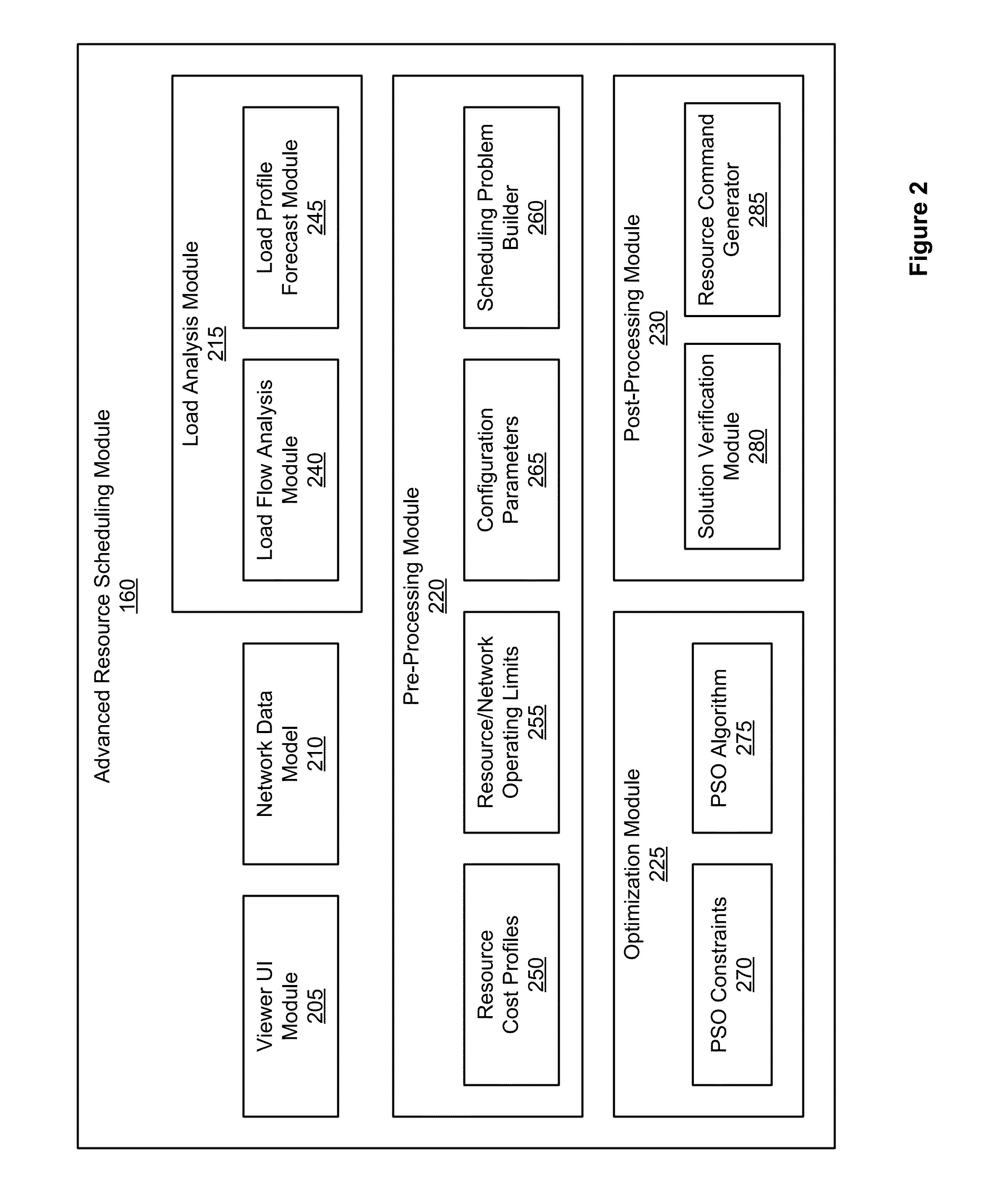
The present disclosure provides for distributed resource scheduling performed by an advanced resource scheduling (ARS) module implemented on a distributed grid management (DGM) server in a power system. The ARS module is configured to automatically generate a resource schedule for controllable distributed energy resources (e.g., resources that are remotely controllable by DGM server and ARS module) in a distribution network of the power system, such as power generation resources and energy storage resources, to provide power in a cost-effective (e.g., optimal) manner. The ARS module is configured to take into account the operating limits of the distributed energy resources (DERs), the cost curves of the DERs, the system load demand, and other operating constraints to determine the most economical operating plan for the DERs, using an optimization technique such as the particle swarm optimization (PSO) algorithm.

Description

FIELD OF THE INVENTION[0001]The present invention relates to power systems, and more particularly, to resource scheduling.BACKGROUND OF THE INVENTION[0002]Meeting energy (or power) demands of customers in a cost-effective way is an age-old problem in the energy utility industry. Traditionally, power has been supplied by bulk generation, where centrally-located power plants provide power through a transmission system to a distribution grid that provides power to end customers. As customers' power demands have evolved and existing systems have aged, additional pressures have been placed on such a traditional bulk generation scheme. For example, a bulk generation power system may be required to meet some quality of service (e.g., power quality, continuity of power, and / or voltage stability), which in turn may require upgrades to be made to a large portion of the bulk generation power system's infrastructure. Such upgrades can be quite expensive.[0003]A modern approach to meeting power ...

Claims


Application Information

Patent Timeline
IPC IPC(8): G05B13/02
CPCG05B13/02G06Q50/06H02J3/008H02J3/28H02J3/30H02J3/32H02J3/381Y02E60/16Y04S10/123Y04S10/14Y04S40/124Y04S50/10H02J3/003H02J2300/10H02J2300/28H02J2300/24H02J13/00016H02J13/00028Y02E10/56Y02E10/76Y02E40/70Y02E60/00Y04S10/50Y04S20/221Y04S20/222Y02B70/30Y02B70/3225H02J3/472Y02E70/30Y04S10/12
Inventor PANDE, SHASHANK ARVINDDROMEY, IAN ROBERT
Owner ORACLE INT CORP
Why Eureka
Try Eureka