
Device and Method for Controlled Motion of a Tool

a technology of controlled motion and tool, applied in the direction of programmed control, manipulators, instruments, etc., can solve the problem that the available devices for cooperative robot control can be extremely expensive, and achieve the effect of selectively preventing the rotational motion of the tool

Active Publication Date: 2014-09-18
ELYTRA TECH
View PDF6 Cites 25 Cited by
  • Summary
  • Abstract
  • Description
  • Claims
  • Application Information

AI Technical Summary

Benefits of technology

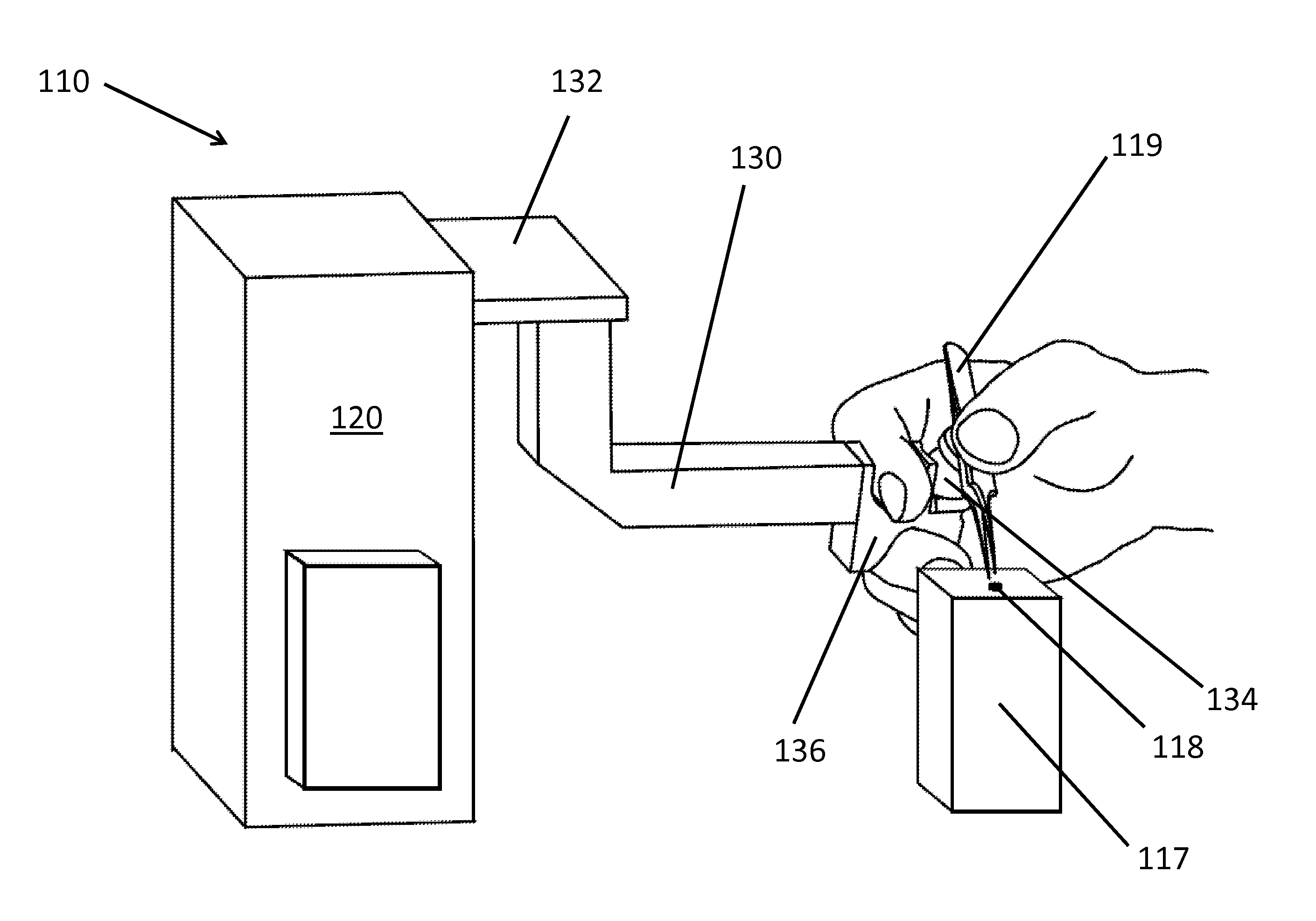
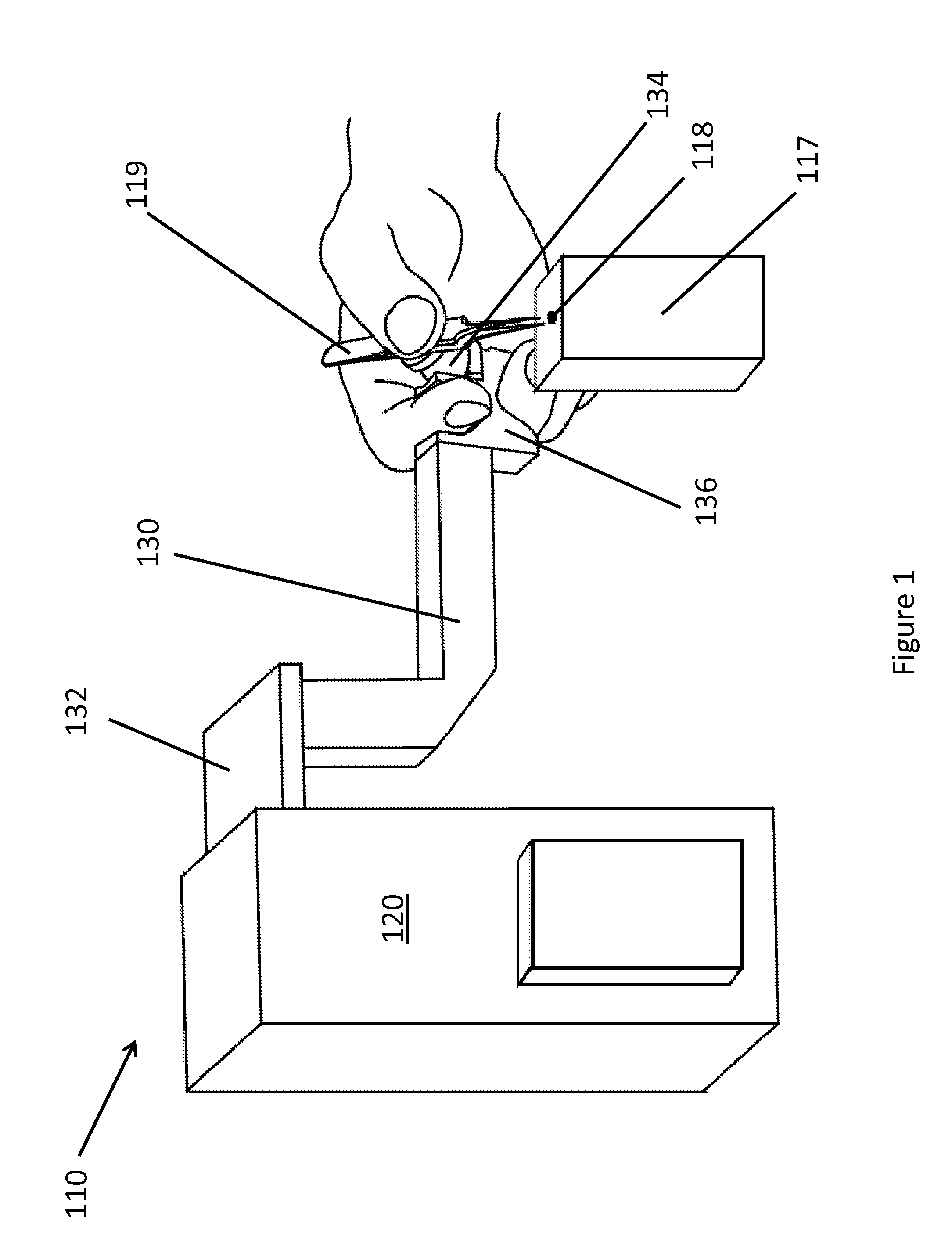
The present invention provides a grip with various components that allow for rotational motion of a tool while maintaining the tool's position and without transferring significant force to the sensor assembly. The grip can be connected to the sensor assembly via a bracket or a rotational housing, and it may include a fixed point mechanism that ensures the tool tip remains stationary relative to the grip. These features improve the accuracy and reliability of the device's performance.

Problems solved by technology

However, currently available devices for cooperative robot control can be extremely expensive.
Further, these devices often provide a high degree of freedom for the tool that is being controlled, at the expense of providing optimal precision and stability.

Method used


Image

  • Device and Method for Controlled Motion of a Tool
  • Device and Method for Controlled Motion of a Tool
  • Device and Method for Controlled Motion of a Tool

Examples


Embodiment Construction

[0026]It is to be understood that the figures and descriptions of the present invention have been simplified to illustrate elements that are relevant for a clear understanding of the present invention, while eliminating, for the purpose of clarity, many other elements found in the field of electromechanical devices, robotics, and the like. Those of ordinary skill in the art may recognize that other elements and / or steps are desirable and / or required in implementing the present invention. However, because such elements and steps are well known in the art, and because they do not facilitate a better understanding of the present invention, a discussion of such elements and steps is not provided herein. The disclosure herein is directed to all such variations and modifications to such elements and methods known to those skilled in the art.

[0027]Unless defined otherwise, all technical and scientific terms used herein have the same meaning as commonly understood by one of ordinary skill i...


PUM


Abstract

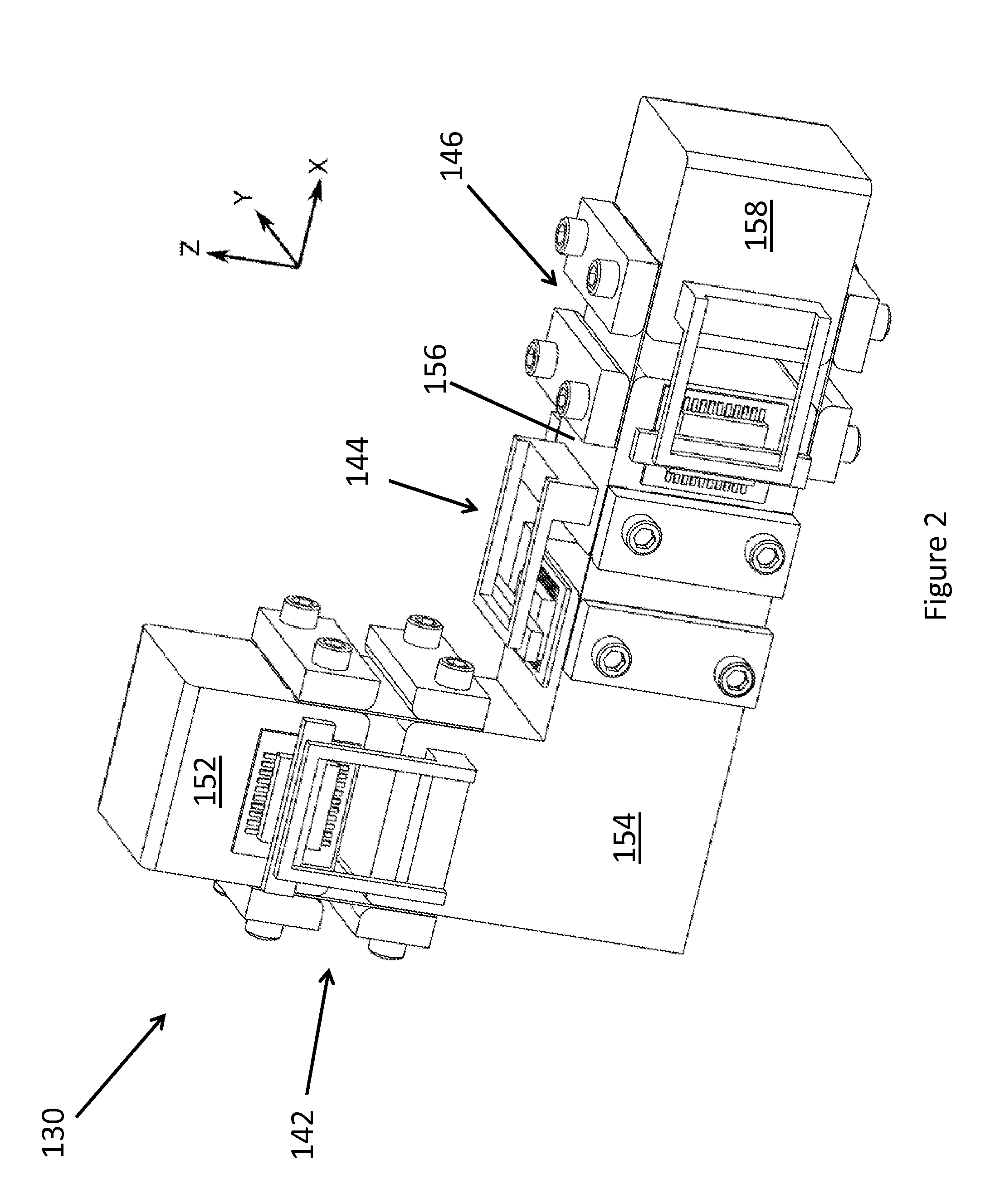
The present invention relates to devices and methods for controlled motion of a tool. In one embodiment, the device can support a tool needed to perform an activity requiring a highly-precise, stable motion, while also accommodating a person's hand for the purposes of moving the tool. In another embodiment, the device of the present invention allows for rotational motion of a tool independently of the directive motion of the tool. In yet another embodiment, the present invention relates to the design of a force transducer useful in a cooperative robot. The device and methods of the present invention are particularly useful for microsurgery or other tasks that are typically performed using cooperative robotics.

Description

CROSS-REFERENCE TO RELATED APPLICATIONS[0001]The present application claims priority to U.S. Provisional Patent Application No. 61 / 784,972 filed Mar. 14, 2013, and U.S. Provisional Patent Application No. 61 / 802,149 filed Mar. 15, 2013, which are incorporated by reference herein in their entirety.BACKGROUND OF THE INVENTION[0002]Cooperative or collaborative robot devices, i.e., cobots, are devices that generally require a human operator to interact physically with the robot to perform a task, such as manipulating a tool, rather than the robot acting relatively autonomously based on little or no human instruction. Such cobots are particularly useful for performing tasks requiring a level of precision that is difficult or impossible for a human to attain without assistance. For example, microsurgery, i.e., surgery requiring manipulation on a sub-millimeter scale, is a task that is particularly well-suited for the use of a cobot device.[0003]Cobot devices and methods currently available...

Claims


Application Information

Patent Timeline
IPC IPC(8): B25J9/16B25J1/02
CPCB25J9/16Y10S901/09B25J1/02B25J9/1682G05B2219/39101G05B2219/39199G05B2219/40415B25J7/00B25J13/085
Inventor ADELMAN, THOMAS L.
Owner ELYTRA TECH
Learn More