Fault tolerant power supply incorporating intelligent load switch to provide uninterrupted power

a load switch and fault-tolerant technology, applied in emergency power supply arrangements, process and machine control, instruments, etc., can solve problems such as significant power loss, reversal of current, and reversal of curren

Active Publication Date: 2014-09-18
ALPHA & OMEGA SEMICON INC
View PDF12 Cites 37 Cited by
  • Summary
  • Abstract
  • Description
  • Claims
  • Application Information

AI Technical Summary

Problems solved by technology

Many electronic systems, such as servers or microservers, require a reliable and uninterrupted source of power.
However, during a fault condition, the drop across the diode can result in significant power loss, especially when the power system is operating at a high current level, such as the current level often required by micro-servers and other hardware in telecommunication applications, which can be well above 80 A.
The MOSFET OR'ing scheme provides lower power loss and improves efficiency during “backup” events but can be disadvantageous during the unlikely event that the secondary (redundant) line's input voltage fails and drops, causing reversal of current since the MOSFET switch allows for bi-directional conduction.
The redundant power supply and the OR'ing circuit increases system cost in addition to consuming real estate space, the cost and space being used for a redundant system that is primarily inactive.
The requirement to include a redundant line increases the complexity of the power supply system as an intelligent controller for the fault detect circuits, current sensing capability for current limiting, current reversal detectors, break before make housekeeping circuits for accurate timing and other aforementioned circuits accessories need to be incorporated in the redundant power supply system.
The complexity of the redundant power supply increases system cost and takes up valuable PC board real estate.

Method used


Image

  • Fault tolerant power supply incorporating intelligent load switch to provide uninterrupted power
  • Fault tolerant power supply incorporating intelligent load switch to provide uninterrupted power
  • Fault tolerant power supply incorporating intelligent load switch to provide uninterrupted power

Examples


Embodiment Construction

[0014]The invention can be implemented in numerous ways, including as a process; an apparatus; a system; and / or a composition of matter. In this specification, these implementations, or any other form that the invention may take, may be referred to as techniques. In general, the order of the steps of disclosed processes may be altered within the scope of the invention.

[0015]A detailed description of one or more embodiments of the invention is provided below along with accompanying figures that illustrate the principles of the invention. The invention is described in connection with such embodiments, but the invention is not limited to any embodiment. The scope of the invention is limited only by the claims and the invention encompasses numerous alternatives, modifications and equivalents. Numerous specific details are set forth in the following description in order to provide a thorough understanding of the invention. These details are provided for the purpose of example and the inv...


PUM


Abstract

A fault tolerant power supply system includes at least one load switch circuit configured to connect, using a main switch, an input voltage to an output node of the load switch circuit when the load switch circuit is turned on and at least one power channel coupled to the load switch circuit to receive the input voltage. The power channel is configured as a buck converter and includes at least a high-side power switch and a low-side power switch. The fault tolerant power supply system is configured to measure a current flowing through the main switch of the load switch circuit, to determine that the current flowing through the main switch of the load switch circuit has exceeded a current limit threshold, and to disable the main switch of the load switch circuit and the low-side power switch of the power channel in response to the determination that the current flowing in the main switch has exceeded the current limit threshold.

Description

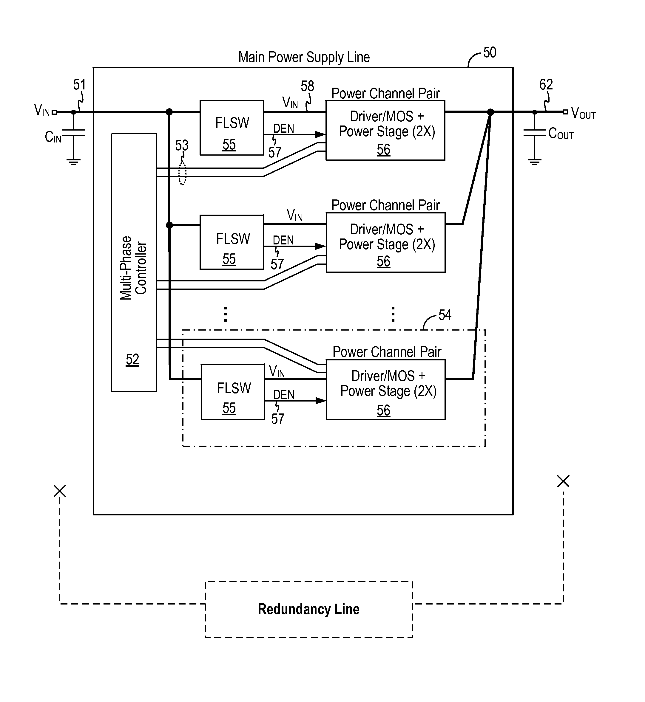
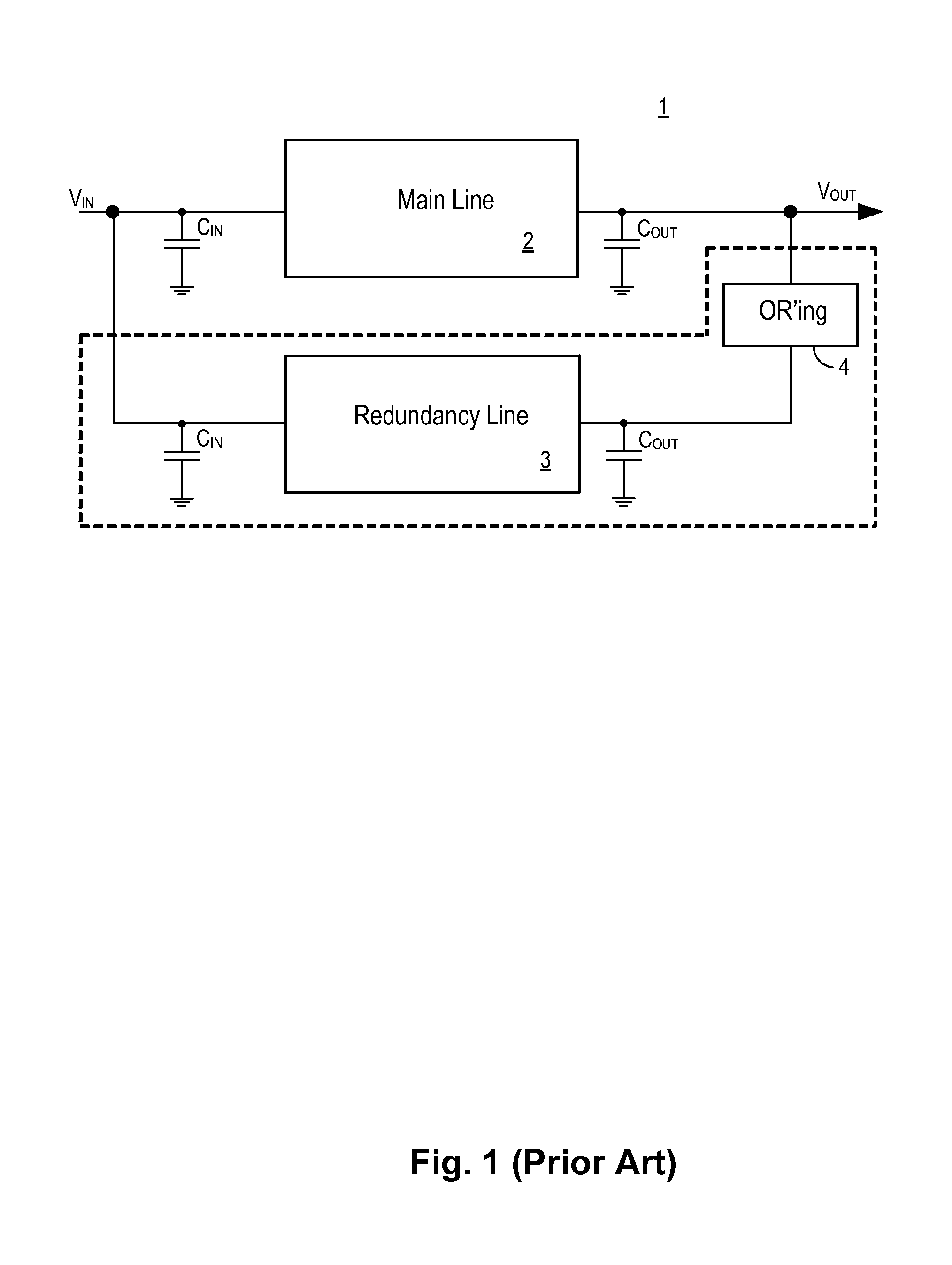
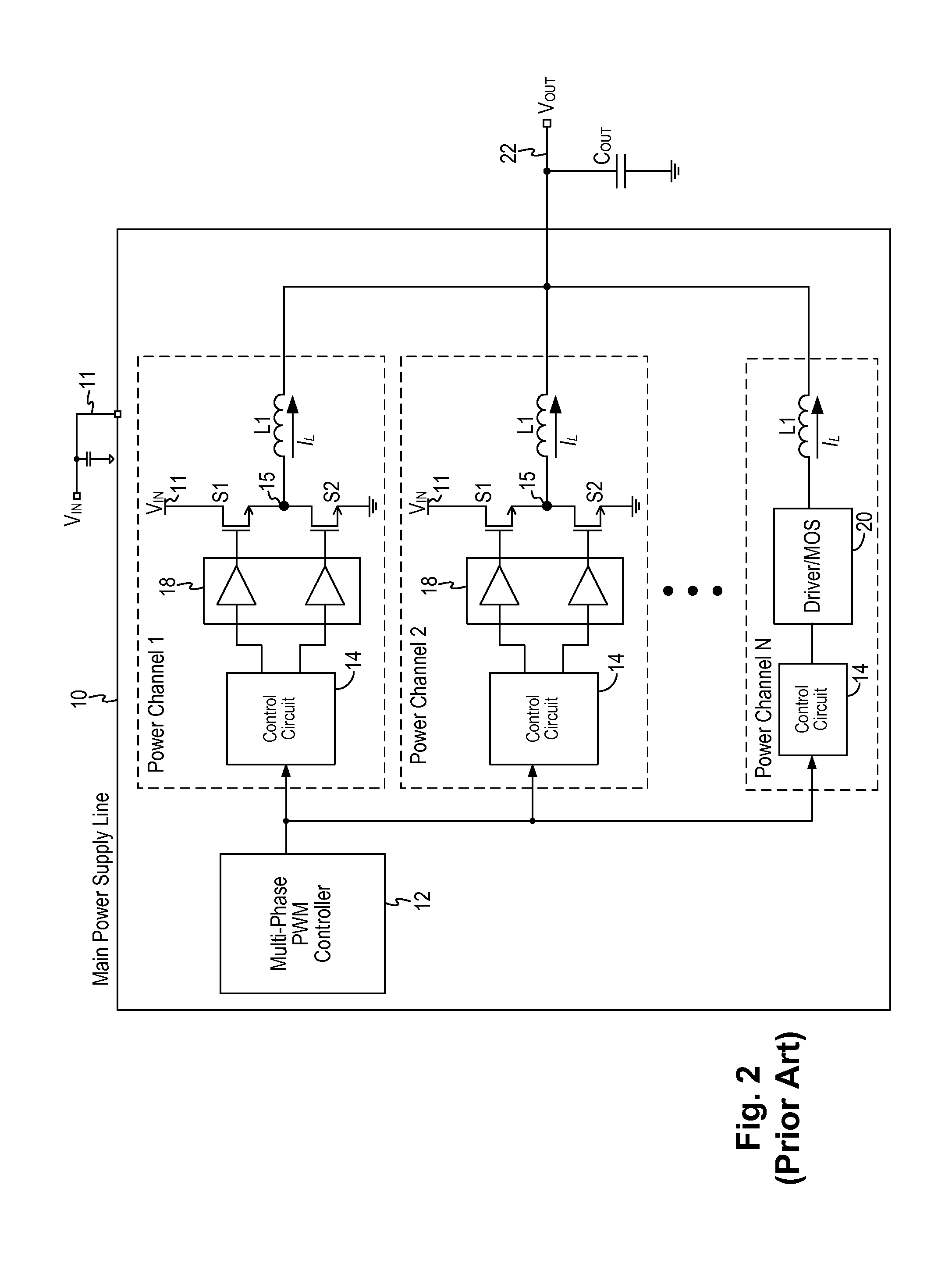
CROSS REFERENCE TO OTHER APPLICATIONS[0001]This application claims priority to U.S. Provisional Patent Application No. 61 / 778,133, entitled FAULT TOLERANT POWER SUPPLY INCORPORATING INTELLIGENT LOAD SWITCH TO PROVIDE UNINTERRUPTED POWER filed Mar. 12, 2013, which is incorporated herein by reference for all purposes.BACKGROUND OF THE INVENTION[0002]Many electronic systems, such as servers or microservers, require a reliable and uninterrupted source of power. In a power supply system providing uninterrupted power supply, backup or redundant power supplies are mounted in parallel with the main power bus line. FIG. 1 illustrates a conventional power supply system where a redundant power supply is coupled in parallel to the main power supply line. Referring to FIG. 1, a power supply system 1 includes a main power supply line 2 and a redundant power supply 3. The redundant power supply 3 is usually mounted in parallel using an OR'ing method, denoted by OR'ing circuit 4. The backup power s...

Claims


Application Information

Patent Timeline
Patent Type & Authority Applications(United States)
IPC IPC(8): H02J4/00
CPCH02J4/00H02J9/061G06F1/26G06F1/305G06F1/30G06F1/28
Inventor TOMAS, MARKZHANG, ZHIYECHANG, ALLENCHANG, KUANG MINGLEE, GILBERTTRAN, SON
Owner ALPHA & OMEGA SEMICON INC
Why Eureka
Try Eureka