
Environmental monitoring device

a monitoring device and environmental technology, applied in the field of environmental monitoring devices, can solve the problems of affecting the use of wireless architecture, unable to enhance computing capabilities, and the majority of existing background electronic devices in people's homes, offices and vehicles, and unable to meet the needs of networking subsystems, etc., and achieves the effect of reducing the barrier to entry and change, and reducing the number of background electronic devices

Inactive Publication Date: 2014-09-18
LEEO
View PDF3 Cites 29 Cited by
  • Summary
  • Abstract
  • Description
  • Claims
  • Application Information

AI Technical Summary

Benefits of technology

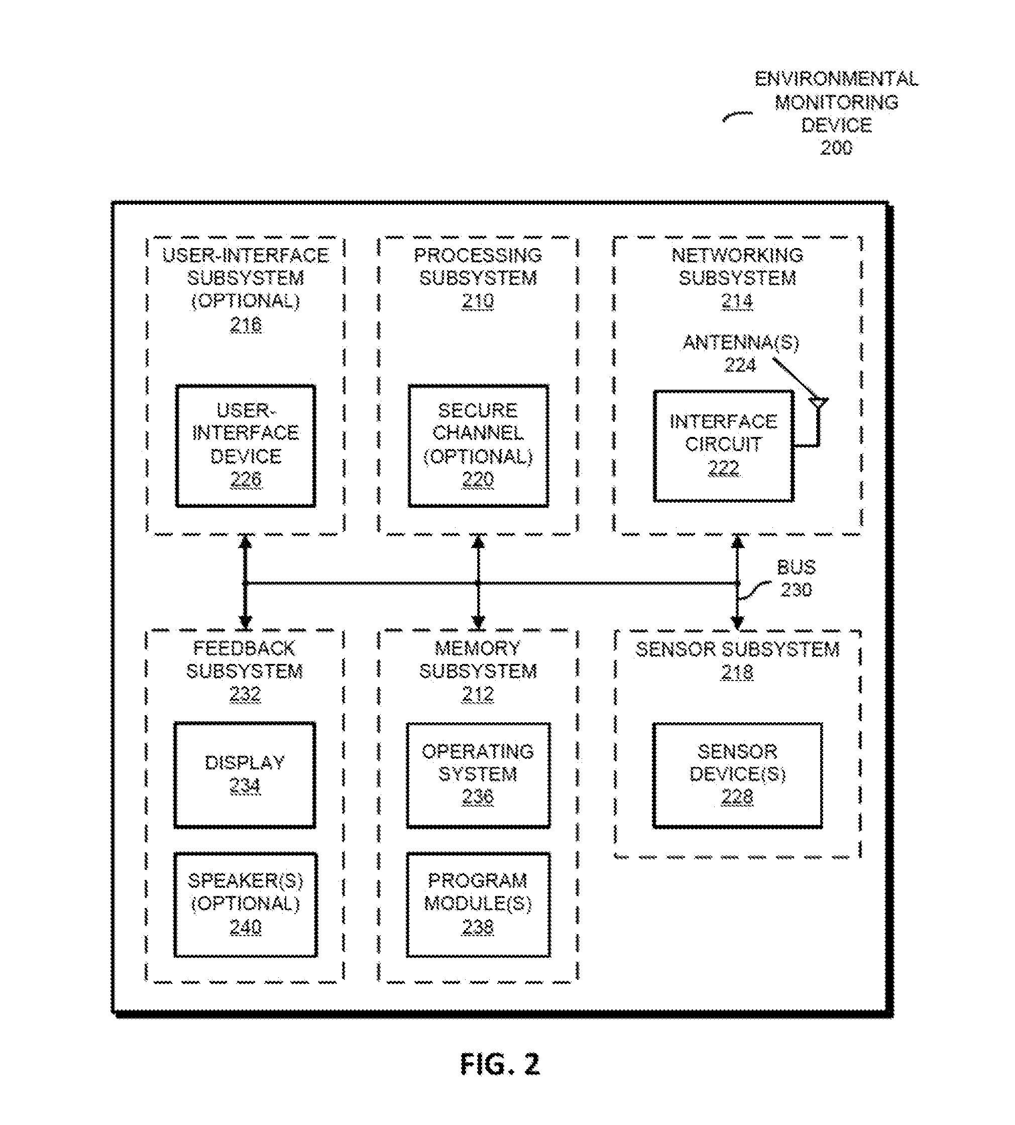
The patent describes an environmental monitoring device that can analyze sensor data from external electronic devices and provide feedback about the operation of those devices. This feedback can be communicated to an aggregation electronic device through an interface circuit and antenna. The sensor data can include information about environmental conditions such as particle count, chemical composition, temperature, humidity, and more. The device can also determine a risk metric for the external environment based on the sensor data and provide insurance or other protection based on the risk metric. The patent also describes a computer-program product and system for implementing the environmental monitoring device.

Problems solved by technology

However, the overwhelming majority of the existing background electronic devices in people's homes, offices and vehicles have neither enhanced computing capabilities (such as processor that can execute a wide variety of applications) nor networking subsystems.
These barriers to entry and change are obstacles to widely implementing the Internet of things.
As a consequence, it may also be difficult to extend the advantages of connectivity and enhanced computing capabilities into these environments.

Method used


Image

  • Environmental monitoring device
  • Environmental monitoring device
  • Environmental monitoring device

Examples


Embodiment Construction

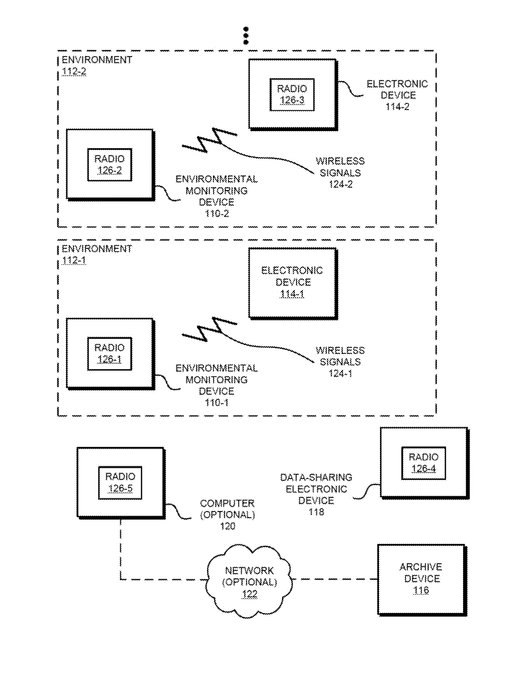
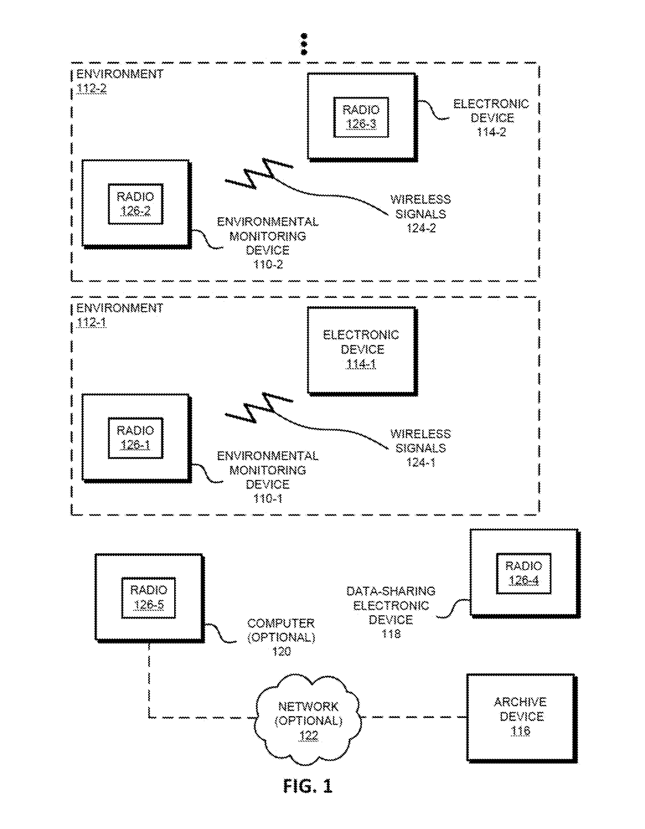
[0090]In one group of embodiments, an environmental monitoring device that monitors the operation of a legacy electronic device is described. In particular, a sensor in the environmental monitoring device provides sensor data (such as temperature, humidity, acoustic information, a particle count, a particle size, etc.) that represents an environmental condition (such as presence of an allergen, fire, flooding, a power outage, an infestation, etc.) in an external environment that includes the environmental monitoring device. This environmental condition is associated with the operation of the legacy electronic device in the external environment (such as a smoke detector, a thermostat, a carbon-monoxide detector, an appliance, a clock, a security alarm, a humidifier, an air filter, a switch, etc.). The environmental monitoring device analyzes the sensor data and provides feedback about the operation of the legacy electronic device based on the analyzed sensor data. Moreover, the senso...


PUM


Abstract

An environmental monitoring device that monitors the operation of a legacy electronic device is described. In particular, a sensor in the environmental monitoring device provides sensor data that represents an environmental condition in an external environment that includes the environmental monitoring device. This environmental condition is associated with the operation of the legacy electronic device in the external environment. The environmental monitoring device analyzes the sensor data and provides feedback about the operation of the legacy electronic device based on the analyzed sensor data. Moreover, the sensor provides the sensor data without or excluding communication and / or electrical coupling between the environmental monitoring device and the legacy electronic device. In this way, the environmental monitoring device facilitates monitoring, analysis and feedback of the sensor data without directly interacting with the legacy electronic device.

Description

CROSS REFERENCE TO RELATED APPLICATION[0001]This application is a continuation of PCT Application No. PCT / US14 / 25742, filed 13 Mar. 2014, which claims priority under 35 U.S.C. §119(e) to U.S. Provisional Application Ser. No. 61 / 802,310, filed on Mar. 15, 2013, both of which are herein incorporated by reference in their entireties.BACKGROUND[0002]1. Field[0003]The described embodiments relate generally to environmental monitoring devices, and more specifically to techniques for providing feedback on the operation of electronic devices in an environment and generating a historical record.[0004]2. Related Art[0005]Trends in connectivity and in portable electronic devices are resulting in dramatic changes in people's lives. For example, the Internet now allows individuals access to vast amounts of information, as well as the ability to identify and interact with individuals, organizations and companies around the world. This has resulted in a significant increase in online financial tra...

Claims


Application Information

Patent Timeline
Patent Type & Authority Applications(United States)
IPC IPC(8): H04L29/06
CPCH04L63/10H04Q2209/10H04Q2209/40H04Q9/00G08B5/36G08B25/007G06F16/113G06Q10/0635G08B23/00G06F21/64G08C19/00H04L9/0861H04L2209/72G05B15/02G06F21/6218
Inventor GETTINGS, ADAM M.STEVENS, ANDREW G.HOVLAND, BJORN H.
Owner LEEO
Learn More