Method and Apparatus for Initiating Coil Defrost in a Refrigeration System Evaporator

a technology of evaporator and refrigeration system, which is applied in the direction of defrosting, domestic cooling apparatus, refrigeration machines, etc., can solve the problems of compromising system performance, wasting energy and cost money, and varying the amount of water vapor in the air in the refrigerated area, so as to achieve less expensive implementation, more accurate, reliable

Active Publication Date: 2014-09-25
EVAPCO
View PDF0 Cites 16 Cited by
  • Summary
  • Abstract
  • Description
  • Claims
  • Application Information

AI Technical Summary

Benefits of technology

[0023]According to one embodiment of the invention, there is provided a frost detection system that is more accurate, reliable and less expensive to implement that existing systems.

Problems solved by technology

The problem with prior art timed defrost systems is that the amount of water vapor in the air in the refrigerated area varies depending on a number of factors.
When conditions are not so severe, there are unnecessary defrost cycles which waste energy and cost money.
Conversely, if the timer is set for modest conditions, and actual conditions are more severe, then defrost cycles could be delayed beyond when they are needed thereby compromising system performance.
The problem with systems that initiate defrost cycles based on power consumption, such as that disclosed in the '792 and '949 patents, is that factors other than frost buildup also impact the power requirements for a fan motor.
The system described in the '949 patent also has the disadvantage that the characteristics of refrigeration system components vary with age and loss of refrigerant.
Such a system cannot compensate for these factors.
The problem with frost detection systems that rely on photoelectric sensors, such as that disclosed in the '971 patent, is that they are only capable of sensing frost at a particular location on an evaporator.
As frost buildup is not always regular or uniform, frost may build at locations away from the photoelectric sensor and not be detected.
This will cause the evaporator to operate inefficiently because defrosting may be needed even though it is not detected due to the location of the sensors.
Another deficiency of such systems is that they may not detect the buildup of transparent, clear ice.
The system in the '833 patent suffers from similar location-dependent deficiencies.

Method used


Image

  • Method and Apparatus for Initiating Coil Defrost in a Refrigeration System Evaporator
  • Method and Apparatus for Initiating Coil Defrost in a Refrigeration System Evaporator
  • Method and Apparatus for Initiating Coil Defrost in a Refrigeration System Evaporator

Examples


Embodiment Construction

[0035]The following description is of a particular embodiment of the invention, set out to enable one to practice an implementation of the invention, and is not intended to limit the preferred embodiment, but to serve as a particular example thereof. Those skilled in the art should appreciate that they may readily use the conception and specific embodiments disclosed as a basis for modifying or designing other methods and systems for carrying out the same purposes of the present invention. Those skilled in the art should also realize that such equivalent assemblies do not depart from the spirit and scope of the invention in its broadest form.

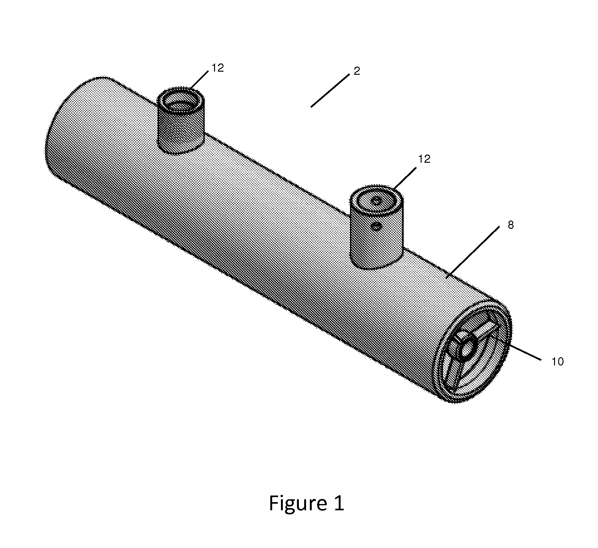
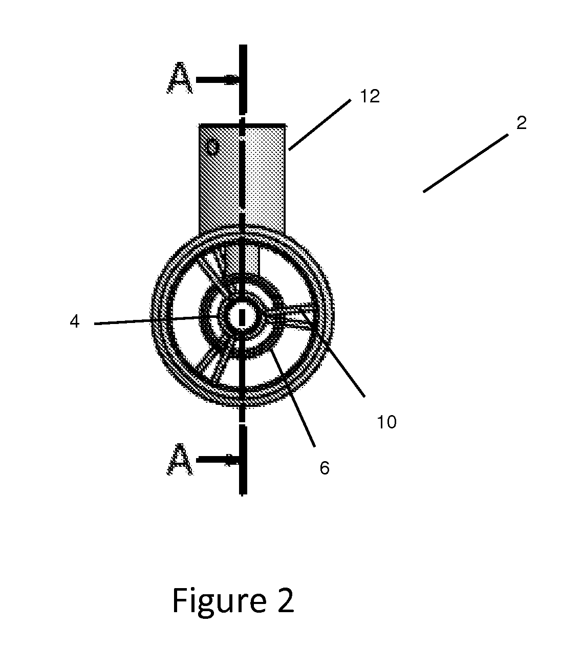
[0036]FIG. 1 shows a sensor 2 according to one embodiment of the invention. The sensor shown in FIG. 1 works on the basis of capacitance change due to the amount of liquid refrigerant between two charged plates. As mentioned above, this is only one embodiment of the invention according to which the amount of liquid refrigerant in the coil or lea...


PUM


Abstract

A system for controlling the defrost cycle of an evaporator comprising a sensor in the coil of an evaporator or downstream of the coil, the sensor configured to determine changes in the liquid mass ratio of the refrigerant in the evaporator. The difference in liquid mass ratio relating to frost buildup on the outside of said evaporator. When the difference in liquid mass ratio reaches a predetermined amount, corresponding to an unsatisfactory frost buildup, a defrost cycle is initiated. When the liquid mass ratio returns to a value that corresponds to a defrosted evaporator, the defrost cycle is discontinued.

Description

FIELD OF THE INVENTION[0001]This invention relates primarily to industrial or commercial refrigeration systems. Specifically, this invention relates to systems for detecting an accumulation of frost on an evaporator and initiating a defrost cycle when the accumulation of frost reaches unacceptable levels.BACKGROUND OF THE INVENTION[0002]Conventional refrigeration systems achieve cooling by allowing a refrigerant such as ammonia or a fluorocarbon to evaporate in the coils of an evaporator. As the refrigerant evaporates, it absorbs heat from the surrounding area. A fan or other air moving device is used to draw air through the evaporator so that heat is removed more effectively from the air in the space that is being refrigerated.[0003]As the temperature in the evaporator is generally below the freezing point of water, water vapor in the air often condenses on the evaporator coils and solidifies as frost. The buildup of frost adversely affects the cooling efficiency of the evaporator ...

Claims


Application Information

Patent Timeline
Patent Type & Authority Applications(United States)
IPC IPC(8): F25D21/02
CPCF25D21/02F25B2700/11F25D21/006F25B2500/19
Inventor DEROSIER, GREG
Owner EVAPCO
Why Eureka
Try Eureka