Tire shape inspection method and tire shape inspection apparatus

a tire shape and inspection method technology, applied in the direction of instruments, ways, instruments, etc., can solve problems such as shape defects, bulges or dents, and achieve the effect of reliably inspecting the sidewall surface of the tire for defective unevenness

Active Publication Date: 2014-09-25
KOBE STEEL LTD
View PDF7 Cites 23 Cited by
  • Summary
  • Abstract
  • Description
  • Claims
  • Application Information

AI Technical Summary

Benefits of technology

[0043]With the tire shape inspection method and the tire shape inspection apparatus according to the present invention, it is possible to reliably inspect a sidewall

Problems solved by technology

In inspection, a tire with a shape defect, such as a bulge or dent, needs to

Method used


Image

  • Tire shape inspection method and tire shape inspection apparatus
  • Tire shape inspection method and tire shape inspection apparatus
  • Tire shape inspection method and tire shape inspection apparatus

Examples


Embodiment Construction

[0054]Embodiments of the present invention will now be described with reference to the drawings.

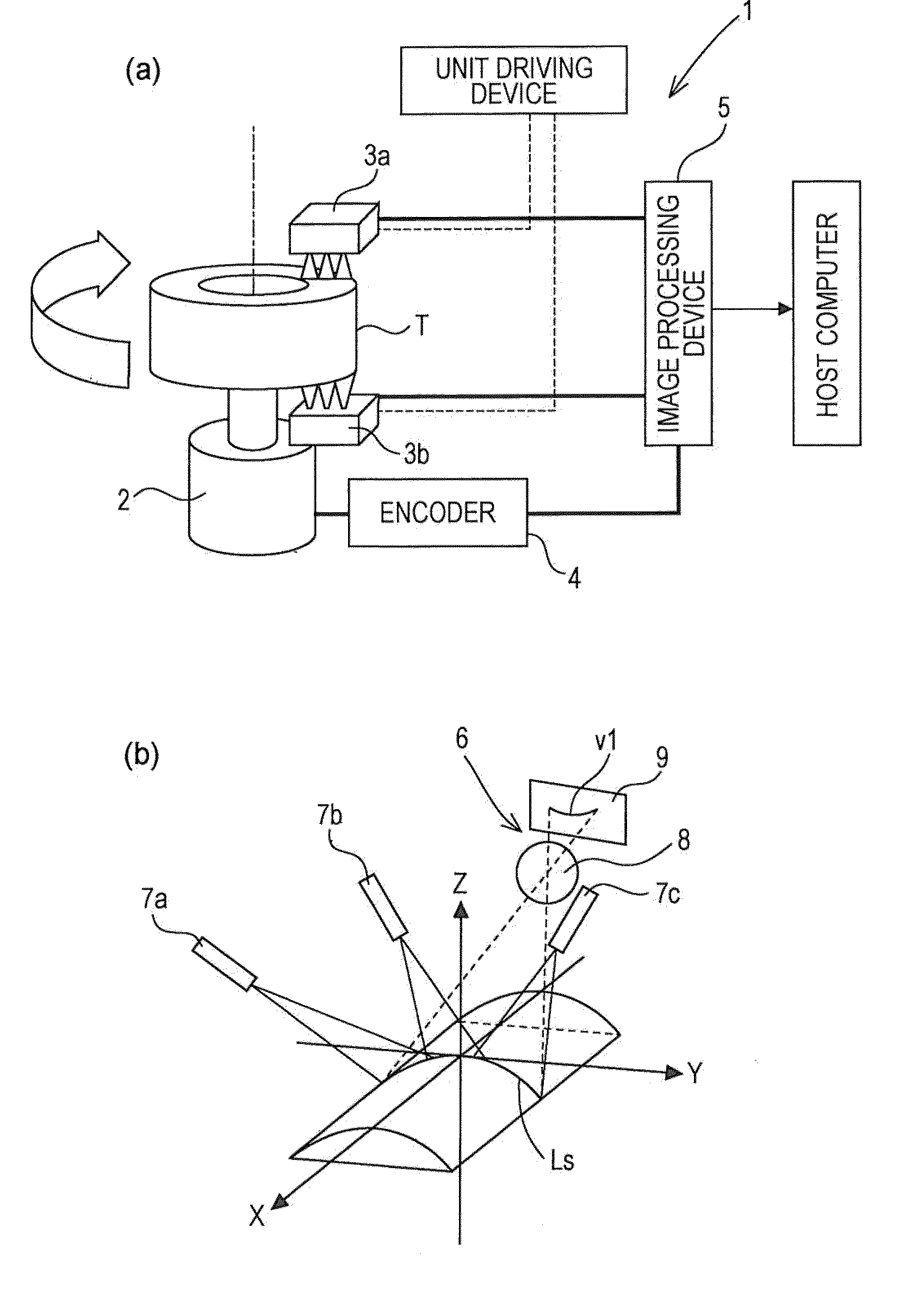
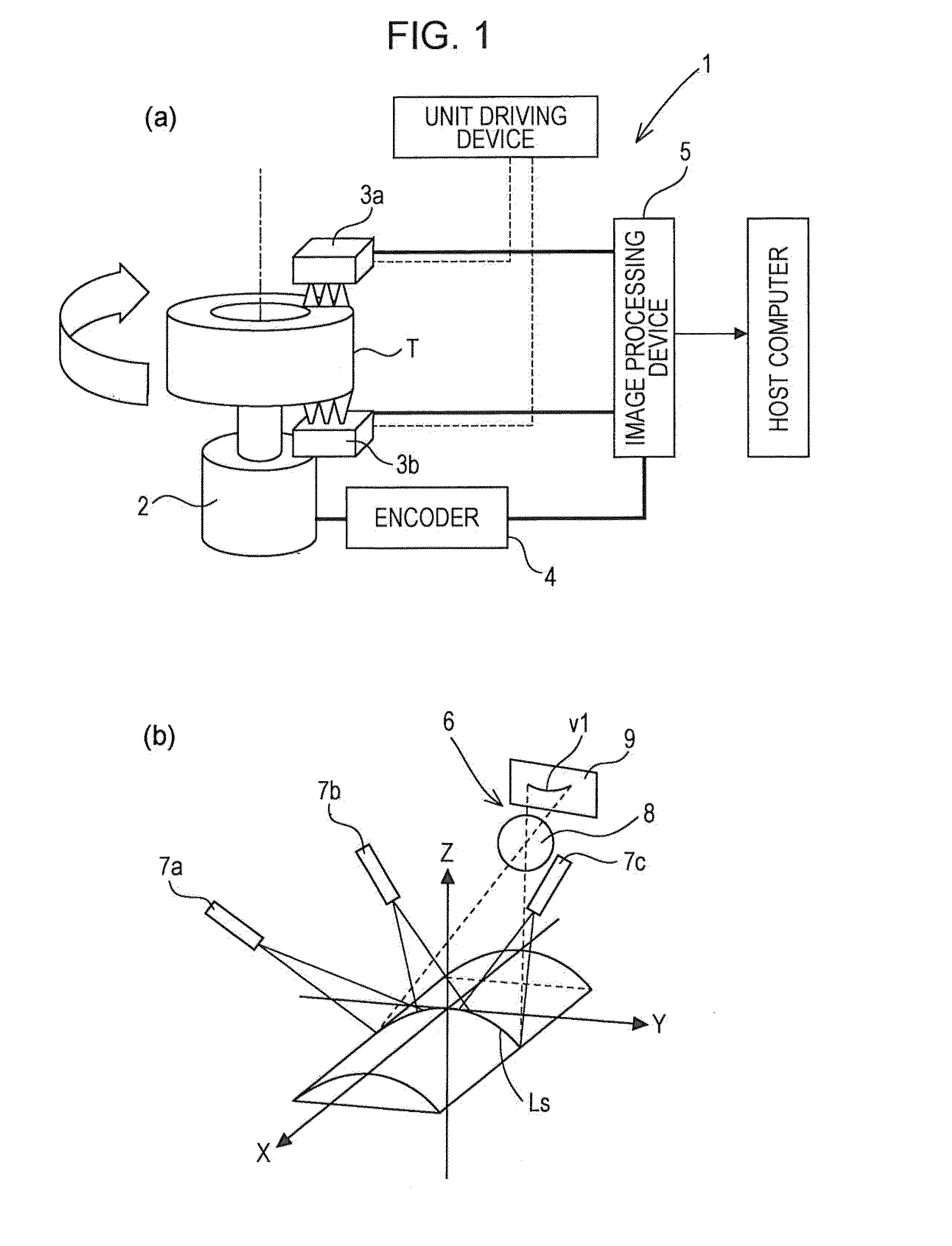
[0055]A tire shape inspection apparatus 1 according to an embodiment of the present invention picks up an image of line light projected onto a surface of a rotating tire T with a camera, and measures a height of each part of the tire T by performing shape detection by a light section method on the basis of the picked-up image. Next, the tire shape inspection apparatus 1 substitutes the measured height of each part of the tire T with the corresponding brightness value and obtains a two-dimensional image (inspection image) of the surface of the tire T.

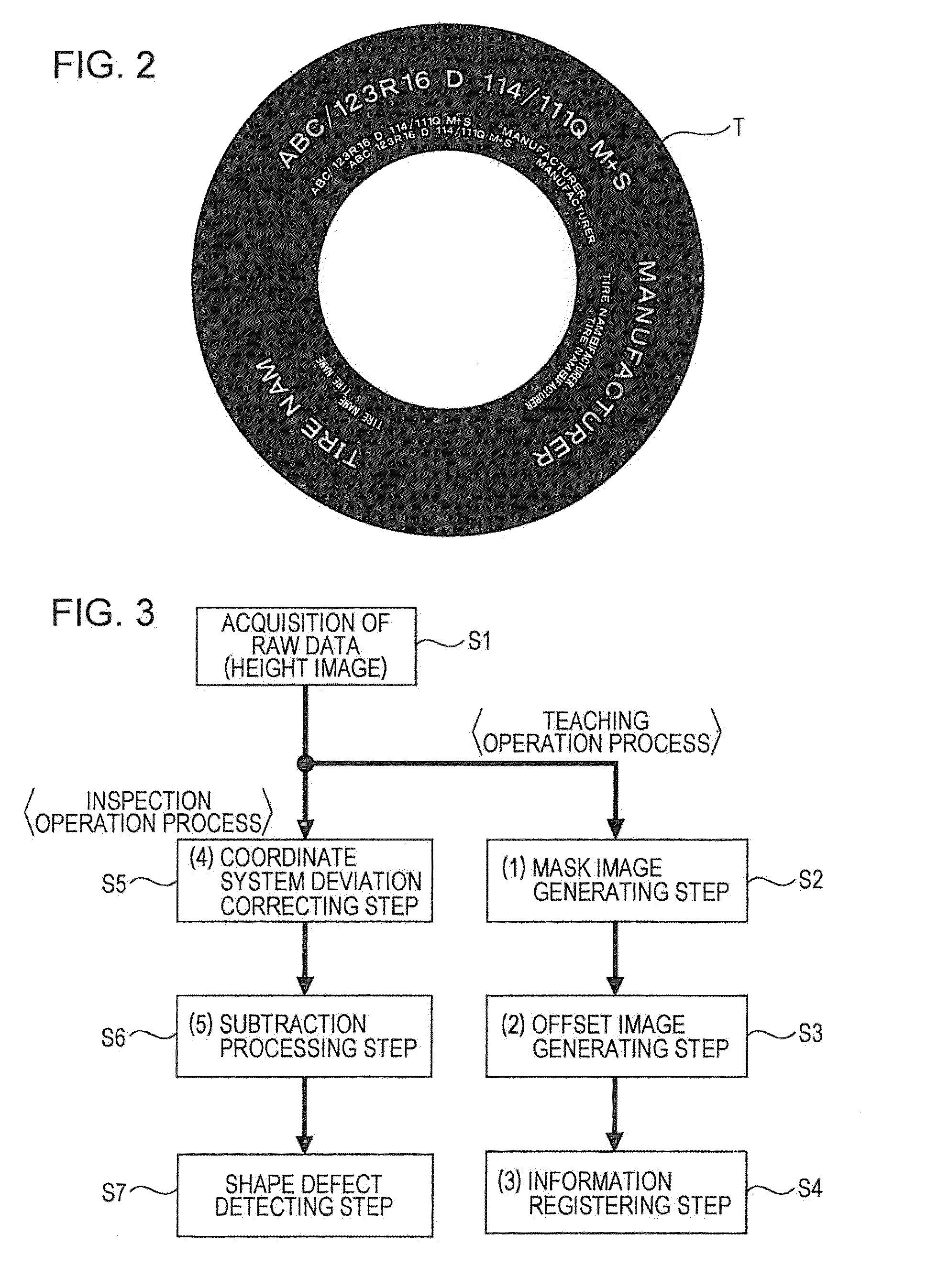
[0056]Next, the tire shape inspection apparatus 1 removes indication marks in a sidewall surface (base surface) on the basis of a “mask image” and a “height offset image” generated in advance by using the “inspection image” described above and a “sample original image” obtained by picking up an image of a sample tire (free from defects). Then,...


PUM


Abstract

A tire shape inspection method executes the following steps: first, as a teaching operation step, boundary lines of the bulge and dent marks are detected in a sample source image of a sample tire, a mask image is generated which denotes the boundary lines, regions are removed from the sample source image which correspond to the boundary lines which are denoted in the mask image, and a height offset image is generated which represents the heights of the remaining regions with one or more offset values. Next, as an inspection operation step, the height offset image is subtracted from an inspection image of the inspection tire, the boundary regions which the mask image represents are removed, and, on the basis of the obtained bulge/dent removal image, shape defects of the sidewall surfaces of the inspection tire are inspected.

Description

TECHNICAL FIELD[0001]The present invention relates to a tire inspection technique, and particularly relates to a tire shape inspection method and apparatus for inspecting a sidewall surface for shape defects by using an image processing technique, the sidewall surface having uneven (embossed) marks therein.BACKGROUND ART[0002]A tire has a structure formed by stacked layers of various materials, such as rubber, chemical fibers, and steel cords. If this layered structure has a non-uniform portion and the tire is filled with air, a raised portion called “bulge”, or a recessed portion called “dent” or “depression”, is formed in an area where resistance to pressure is relatively weak. In inspection, a tire with a shape defect, such as a bulge or dent, needs to be excluded from shipment due to safety concerns or problems with appearance.[0003]Therefore, in the final stage of tire production (i.e., in an inspection step after tire vulcanization), tire surfaces, particularly sidewall surfac...

Claims


Application Information

Patent Timeline
IPC IPC(8): G01M17/02
CPCG01M17/02G01B11/245G01B11/2522G01M17/027B60C13/003G01N2021/8887G01N21/9515G06T7/001G06T2207/30108G01B11/25
Inventor TAKAHASHI, EIJITSUJI, TOSHIYUKIKANNAKA, MASATO
Owner KOBE STEEL LTD
Why Eureka
Try Eureka