Pressure response fracture port tool for use in hydraulic fracturing applications

a hydraulic fracturing and port tool technology, applied in the field of hydraulic fracturing, can solve the problems of a second set of flow ports creating a noticeable pressure drop, and achieve the effect of increasing the likelihood of a proper hydraulic fracturing job

Active Publication Date: 2014-09-25
WATSON WELL SOLUTIONS
View PDF4 Cites 22 Cited by
  • Summary
  • Abstract
  • Description
  • Claims
  • Application Information

AI Technical Summary

Benefits of technology

[0007]A pressure response fracture port tool (“the tool”) made according to this invention reliably provides a noticeable indication at surface to an operator as to when the flow port is opened. The tool includes an outer housing and a sliding sleeve which resides within the outer housing. The outer housing has a first and second set of flow ports. The inner mandrel moves between a first position and a third position to expose the flow ports to the wellbore.
[0008]The first set of flow ports, with its smaller area relative to the second set of flow ports, creates a noticeable pressure increase or spike that can be observed at surface when exposed to the wellbore. The second set of flow ports creates a noticeable pressure drop when it is exposed to the wellbore. “Exposed to the wellbore” means that the inner mandrel is no longer blocking fluid flow to the first set (and then second set) of flow ports of the outer housing.
[0009]After the pressure spike and drop are observed, the operator is assured that the fracture zone of interest is now open and flow downstream of the tool is blocked. The pump rate can be increased and the zone can be hydraulic fractured.
[0010]Objects of this invention are to provide a pressure response flow port tool that (1) makes the sliding sleeve method of hydraulic fracturing more reliable than prior art tools which are used for that purpose; (2) increases the likelihood of a proper hydraulic fracturing job along the entire length of the wellbore; (3) provides a noticeable, unambiguous indication to an operator that the fracture zone is open; (4) artificially creates a pressure spike and subsequent pressure drop so that, independent of the formation's characteristics, the pressure spike and drop are noticeable to an operator; and (5) does not require significant changes to be made to current hydraulic fracturing methods or procedures.

Problems solved by technology

The second set of flow ports creates a noticeable pressure drop when it is exposed to the wellbore.

Method used


Image

  • Pressure response fracture port tool for use in hydraulic fracturing applications
  • Pressure response fracture port tool for use in hydraulic fracturing applications
  • Pressure response fracture port tool for use in hydraulic fracturing applications

Examples


Embodiment Construction

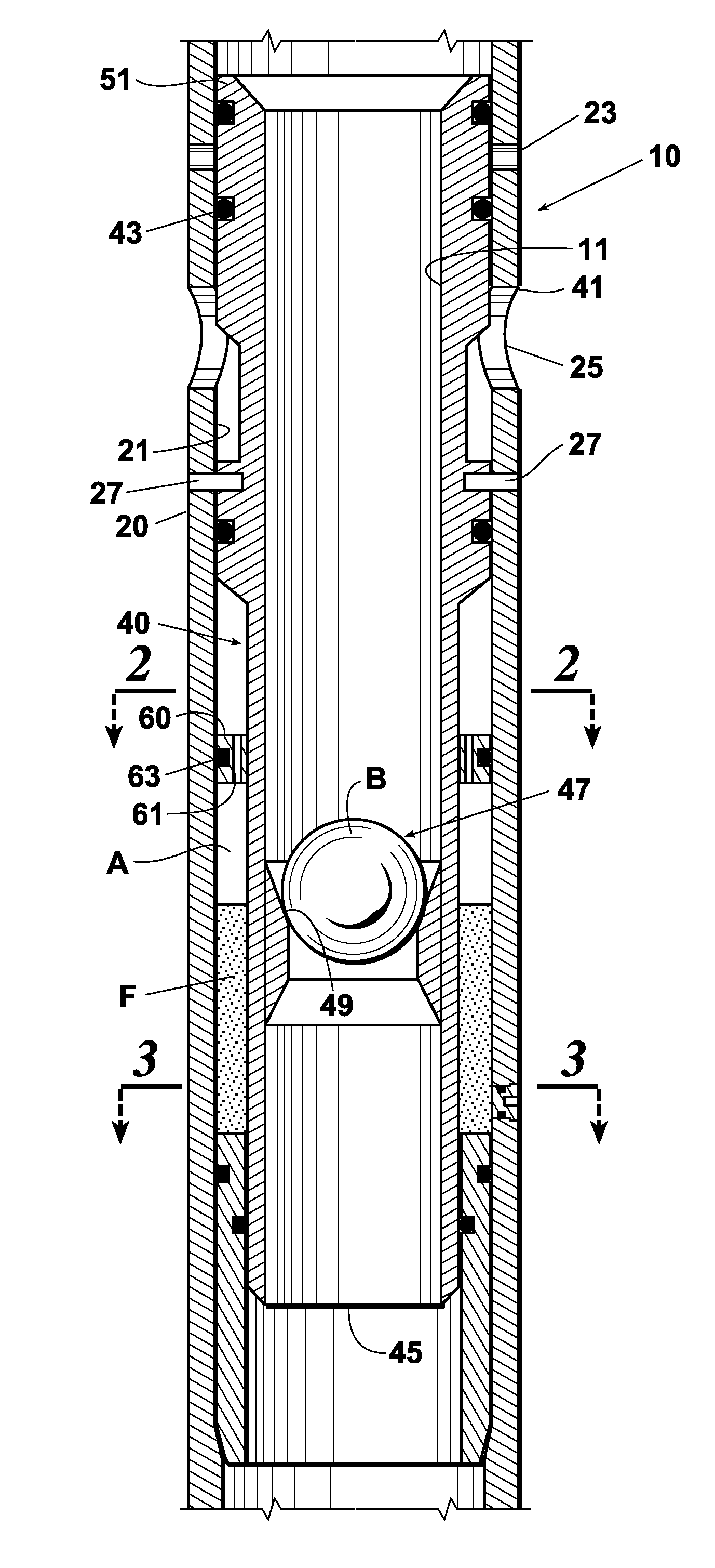
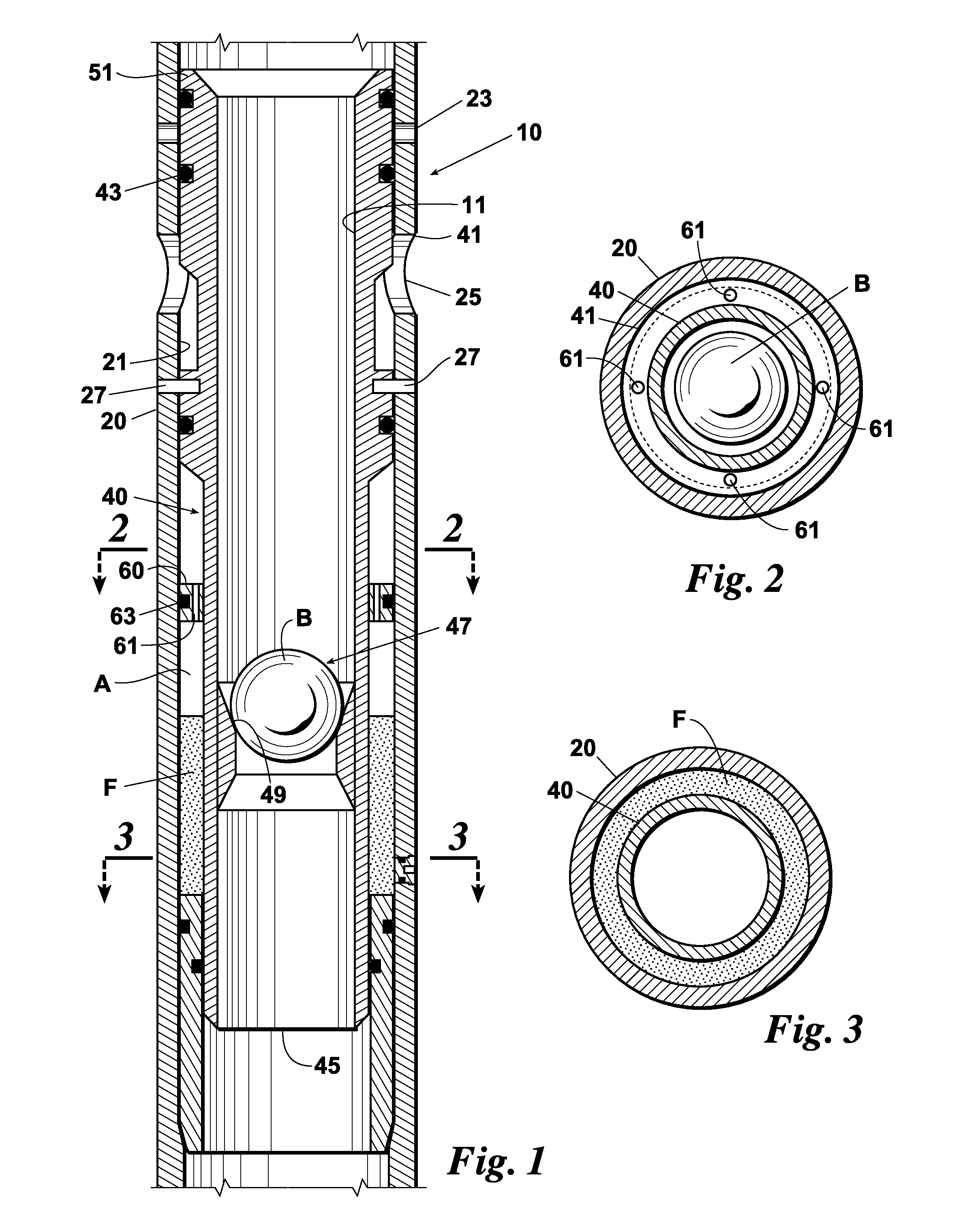
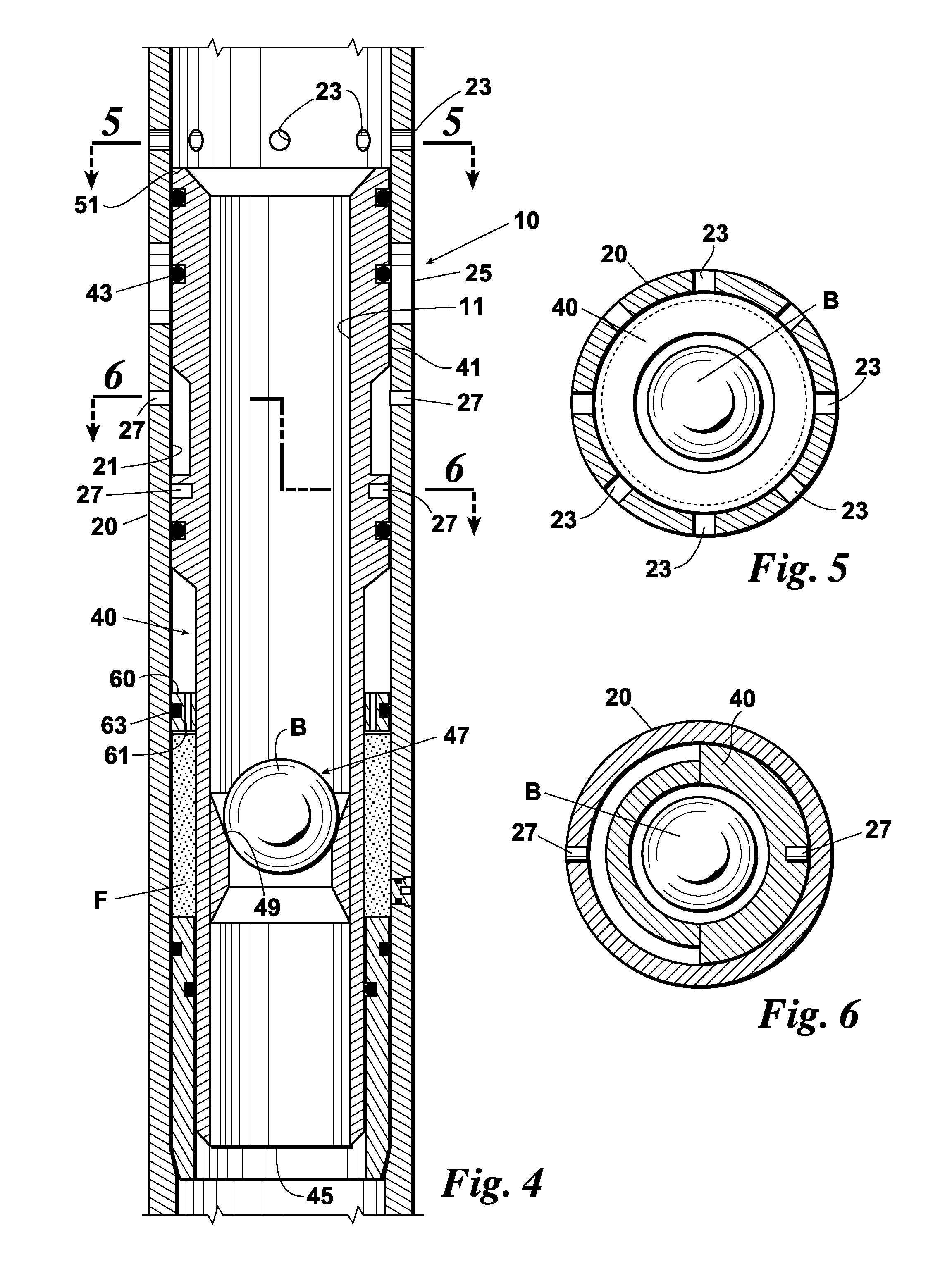
[0040]Referring to the drawings, a pressure response fracture port tool (“the tool”) 10 made and used according to this invention includes an outer housing 20 having a first and second set of flow ports 23, 25 (see FIG. 1) and a sliding sleeve or inner mandrel 40 which initially covers the ports 23, 25 and then exposes each set of flow ports 23, 25 in turn (see FIGS. 4 & 7).

[0041]“Exposed to the wellbore” means that the inner mandrel is no longer blocking fluid flow to the first set (and then second set) of flow ports of the outer housing.

[0042]The inner mandrel 40 is initially held in relation to the outer housing 20 by a set of shear pins 27 so that in a first position the mandrel 40 covers the first and second set of flow ports 23, 25 located in the outer housing 20. O-ring type seals 43, of a kind well known in the art, provide sealing engagement between the inner wall 21 of the housing 20 and the outer wall 41 of the inner mandrel 40.

[0043]When the tool 10 is deployed downhole ...


PUM


Abstract

A pressure response fracture port tool and method for its use reliably provides a noticeable indication at surface to an operator as to when the flow port is opened. The tool includes an outer housing and a sliding sleeve which resides within the outer housing. The outer housing has a first and second set of flow ports. The inner mandrel moves between a first position and a third position to expose the flow ports to the wellbore. The first set of flow ports, with its smaller area relative to the second set of flow ports, creates a noticeable pressure increase or spike that can be observed at surface when exposed to the wellbore. The second set of flow ports creates a noticeable pressure drop when it is exposed to the wellbore.

Description

CROSS REFERENCE TO PENDING APPLICATIONS[0001]This application claims priority to U.S. Prov. Pat. Appl. Ser. No. 61 / 724,412, filed on Nov. 9, 2012.BACKGROUND OF THE INVENTION[0002]This invention relates generally to hydraulic fracturing and, more particularly, to downhole tools and methods used in the sliding sleeve method of hydraulic fracturing.[0003]Hydraulic fracturing creates fractures in a reservoir rock formation in order to release oil and natural gas products from that formation. The two most common methods of creating the fractures are the “plug” method (or “plug-and-perf” method) and the “sliding sleeve” method.[0004]One of the challenges with the sliding sleeve method is the occasional failure of the ball to reach or seat properly in the sliding sleeve of the next flow port or zone and, therefore, not open that fracture zone. The operator in the fracking rig often cannot tell if the flow port is open because formation characteristics vary along the wellbore, thereby makin...

Claims


Application Information

Patent Timeline
Patent Type & Authority Applications(United States)
IPC IPC(8): E21B34/14E21B43/26
CPCE21B43/26E21B34/14E21B23/04E21B2200/06E21B34/103E21B34/142
Inventor WATSON, ROGERDAHL, NEVIN
Owner WATSON WELL SOLUTIONS
Why Eureka
Try Eureka