Clean out sub

a sub and vacuum technology, applied in the direction of sealing/packing, wellbore/well accessories, construction, etc., can solve the problem of rapid shift of the spool, achieve the effect of reducing the pressure area of the valve spool down the orifice, and increasing the pump rate and corresponding annular velocities

Active Publication Date: 2017-07-18
WWT NORTH AMERICA HLDG
View PDF40 Cites 4 Cited by
  • Summary
  • Abstract
  • Description
  • Claims
  • Application Information

AI Technical Summary

Benefits of technology

[0007]The present invention provides a tool that could open additional ports to annulus which allows the operator to achieve increased pump rates and corresponding annular velocities. The present invention includes a clean out sub capable of repeatedly opening and closing annular circulation ports to provide increased pump rates and corresponding annular velocities for the drilling fluid. The clean out sub has two distinct modes of operation, namely, annular circulation ports open and annular circulation ports closed. The clean out sub contains a valve spool that responds to differential pressure created across a fixed orifice. The force created by the differential pressure pushes the valve spool into a compression spring. The surface area of the spool that system pressure acts on is equal above and below the orifice. By doing this, the valve spool position is only affected by increasing or decreasing the flow rate and corresponding pressure drop created by the orifice. Changes in system pressure, such as back pressure created by motor work downhole of the clean out sub will have no effect on the valve spool position. At a predetermined flow rate the valve spool will move far enough to shut off pressure to the spring cavity. When the pressure to the spring cavity is shut off, the pressure area of the valve spool downhole of the orifice is reduced substantially because the spring cavity is vented to annulus through a bleed hole. This creates a large force imbalance on the valve spool which quickly overwhelms the spring force and causes the spool to rapidly shift revealing the annular circulation ports. The valve snapping open eliminates spool oscillation which is a source of potential wear. The annular circulation ports are angled uphole in a swirl arrangement to better lift debris off the bottom of the hole. The annular circulation ports will remain open until the pressure to the spring cavity is reintroduced at a predetermined pump rate. This will be at a considerably lower pump rate than when the clean out sub opens because of the pressure area imbalance on the spool. The valve hysteresis is beneficial for high pressure wells where an elevated pump rate is not possible. The operator can briefly increase the pump rate to shift the clean out sub, then reduce down to normal pump rate. The annular circulation ports will remain open and improved hole cleaning is achieved by the swirling fluid jetting from the ports.

Problems solved by technology

This creates a large force imbalance on the valve spool which quickly overwhelms the spring force and causes the spool to rapidly shift revealing the annular circulation ports.

Method used


Image

  • Clean out sub
  • Clean out sub
  • Clean out sub

Examples


Embodiment Construction

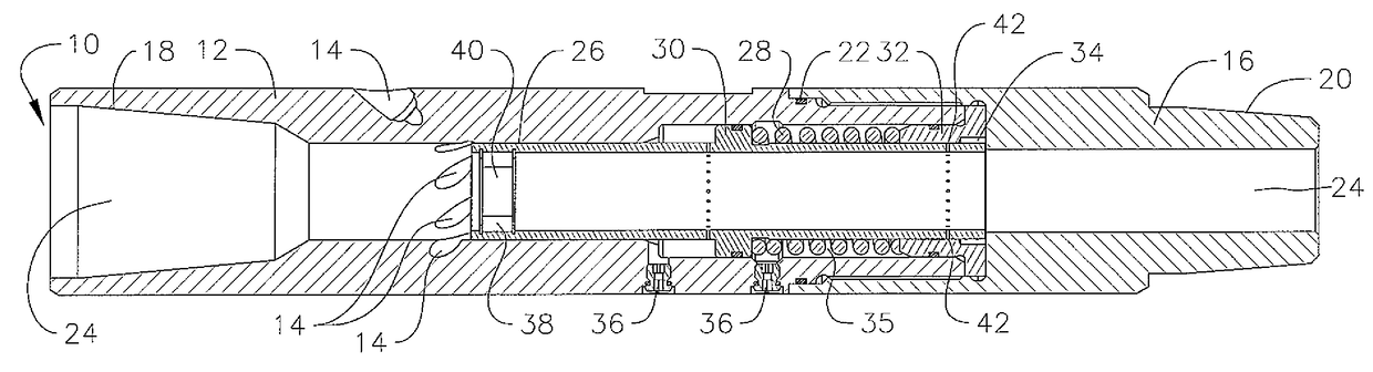
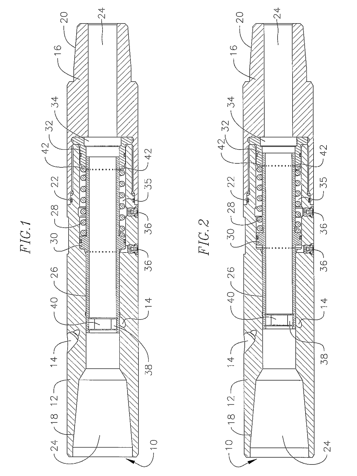
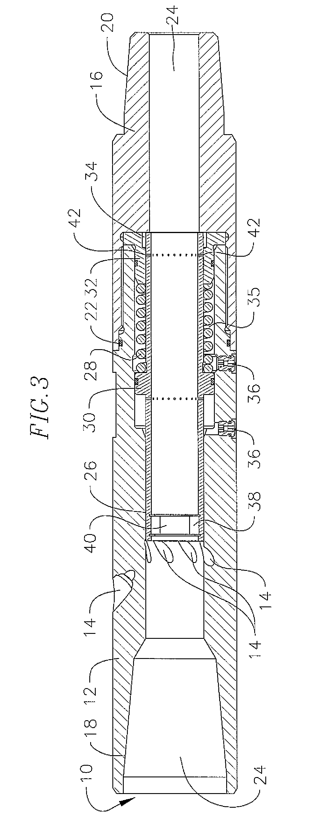
[0014]FIG. 1 illustrates a clean out sub 10 of the present invention. The clean out sub includes a cylindrical housing 12 having a plurality of annular circulation ports 14 positioned circumferentially around the housing 12. The ports are angled uphole in a swirl arrangement. The housing is connected to a tool joint 16, typically by being threaded together. The uphole end 18 of the housing is adapted to be attached to the drill string, typically by threading. Similarly, the downhole end 20 of the tool joint is also adapted to be connected to further drill string components, such as a motor, typically by threading. Similarly, the housing and the tool joint are connected to one another by threading. A seal 22 is positioned between the downhole end of the housing and the uphole end of the tool joint. A fluid passage 24 extends through the housing and tool joint. A valve spool 26 is positioned within the fluid passage 24 of housing 12 and a compression spring 28 is positioned around a p...


PUM


Abstract

A clean out sub for use in a drill string having a tool body with a cavity for passage of drilling fluid and annular fluid circulation ports extending through the tool body, a valve spool is positioned within the tool body cavity having a reduced diameter orifice, a compression spring is located within the tool body cavity adjacent the valve spool, wherein a drop in fluid pressure created by the orifice imparts a downhole force on the valve spool and at a predetermined force overcomes a set resistive force of the compression spring thereby moving the valve spool to open the annular fluid circulation ports.

Description

CROSS-REFERENCE TO RELATED APPLICATION(S)[0001]This Patent Application claims priory to and the benefit of U.S. Provisional Patent Application Ser. No. 61 / 836,951, filed on Jun. 19, 2013, entitled CLEAN OUT SUB, the entire content of which is hereby expressly incorporated by reference.BACKGROUND OF THE INVENTION[0002]Wells are drilled with a fluid driven motor affixed to the lower end of a drill pipe. Drilling fluid is pumped down through the drill pipe by pumps situated at the surface of the drill string. The drilling fluid pumped downhole through the drill pipe passes through the motor and for any given motor, there is an optimum flow rate along with minimum and maximum allowable flow rates. After passing through the motor, the drilling fluid passes through a drill bit or other cutting tool before passing back up the annulus of the wellbore around the drill string.[0003]Downhole operations routinely encounter pump rate limitations due to surface pressures exceeding the capacity of...

Claims


Application Information

Patent Timeline
Patent Type & Authority Patents(United States)
IPC IPC(8): E21B21/10E21B37/00E21B34/10E21B34/00
CPCE21B21/103E21B34/10E21B37/00E21B2034/007E21B2200/06
Inventor O'NEAL, ERIC JOHNKRUEGER, V, RUDOLPH ERNSTTROWBRIDGE, ANDREW ALEXANDER
Owner WWT NORTH AMERICA HLDG
Why Eureka
Try Eureka