Vacuumizing hole of vacuum glass and manufacturing method thereof

A technology of vacuum glass and air extraction port, which is applied in glass forming, glass re-forming, glass manufacturing equipment and other directions, can solve the problems of weakening the air tightness of solder performance, not necessarily good economic benefits, and complicated vacuuming process, etc. Prolonged service life, simple structure, good air tightness

Inactive Publication Date: 2015-01-21
戴长虹
View PDF8 Cites 4 Cited by
  • Summary
  • Abstract
  • Description
  • Claims
  • Application Information

AI Technical Summary

Problems solved by technology

The disadvantage of the first method is that the vacuuming process is complicated and the production efficiency is very low: because the suction pipe is very thin, the vacuum layer is very thin, the suction resistance is large, the speed is small, and single-chip extraction is required, so the production efficiency is very low; The two methods can solve the shortcomings of the first method, but because the low-temperature glass solder is made of a variety of oxides, under high temperature and vacuum, the air and moisture absorbed by the solder, volatile substances in the solder, and the solder during production The gas dissolved in the process and the decomposition of some oxides in the solder will cause a large number of bubbles in the solder, which will greatly weaken the performance of the solder, especially the air tightness, which will greatly affect the feasibility of this method.
Another method is between the above two methods, that is, prefabricating the air extraction port on the glass, then vacuumizing after sealing the edge at high temperature, and finally using solder to seal and weld the metal sheet on the air extraction port; The disadvantage is that if you use glass solder, you will encounter the same difficulties as the second method. If you use metal solder for brazing, you will encounter great difficulties in how to achieve airtight welding of small and light metal sheets under vacuum conditions. Its economic benefits are not necessarily better than the first way

Method used


Image

  • Vacuumizing hole of vacuum glass and manufacturing method thereof
  • Vacuumizing hole of vacuum glass and manufacturing method thereof
  • Vacuumizing hole of vacuum glass and manufacturing method thereof

Examples


Embodiment 1

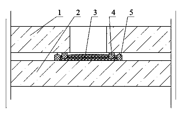
[0061] Embodiment 1: see figure 1 , the vacuum glass is composed of upper glass 1 and lower glass 2, a through hole is drilled on the upper glass 1 to form an air inlet, and the glass is coated or printed on the lower surface of the upper glass 1 and the upper surface of the lower glass 2. Paste or metal paste is printed into a sealing ring concentric with the air suction port, the sealing ring 4 of the upper glass 1 can be inserted into the sealing ring 5 of the lower glass 2, and the air extraction channel is between the two sealing rings; the upper and lower glasses are sent into the Sinter the sealing ring on the upper and lower glass in a high-temperature furnace or tempering furnace, and then use low-temperature glass solder to seal the edges of the combined upper and lower glasses in an atmospheric-pressure high-temperature furnace. After the edge-sealing glass is taken out of the high-temperature furnace, it is Put the metal solder 3 such as tin alloy into the air exha...

Embodiment 2

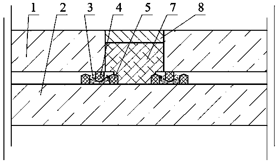
[0062] Example 2: see figure 2 The vacuum glass consists of an upper glass 1 and a lower glass 2. A through hole is drilled on the upper glass 1 to form an air inlet, and glass paste or metal paste is used on the lower surface of the upper glass 1 and the upper surface of the lower glass 2. Bond one or two metal rings or glass rings. When using metal rings, metals with similar thermal expansion coefficients to glass, such as Kovar alloys, are preferred. When using glass rings, it is preferable to coat metal paste to strengthen the sealing effect; The sealing ring 4 of 1 can be inserted between the two sealing rings 5 ​​of the lower glass 2, and the gap between the three sealing rings is an air extraction channel; the upper and lower glasses are sent into a high-temperature furnace or a tempering furnace to sinter the sealing rings on the upper and lower glass Then use low-temperature glass solder to seal the upper and lower glass after assembling in a high-temperature furnace...

Embodiment 3

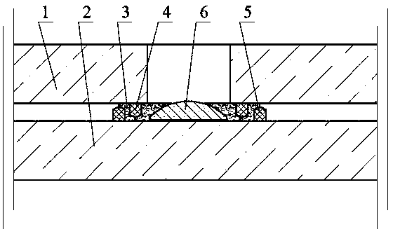
[0063] Embodiment 3: see image 3 , basically the same as Example 2, the difference is that the sealing ring 4 of the upper glass 1 is changed from a metal ring to a metal tube, and the small sealing ring 5 of the lower glass 2 is changed into a convex sheet 6. This embodiment is suitable for thicker vacuum Layers and larger suction openings.


PUM


Abstract

A vacuumizing hole of a vacuum glass is characterized in that the a manufacturing method includes following steps: punching an upper glass of the vacuum glass to form the vacuumizing hole; manufacturing a sealing ring around the vacuumizing hole on the lower surface of the upper glass and manufacturing the sealing ring at the position corresponding to the vacuumizing hole on the upper surface of the lower glass, wherein the sealing ring on the upper glass can be inserted into the sealing ring on the lower glass to form a vacuumizing channel between the two sealing rings; vacuumizing the vacuumizing hole and performing a heating process to enable a metal solder to melt into a liquid which is remained in the sealing ring on the lower glass, wherein the sealing ring on the upper glass is also sunk in the liquid; enabling the vacuumizing hole to seal automatically through a liquid sealing principle; decreasing the temperature to solidifying the liquid to achieve air-tightness sealing of the vacuumizing hole. The method can achieve mass production, can greatly improve production efficient and qualification ratio of a vacuum glass and can reduce production cost.

Description

technical field [0001] The invention belongs to the field of vacuum glass, and in particular relates to a suction port of vacuum glass and a manufacturing method thereof. [0002] Background technique [0003] The existing vacuum glass is generally composed of two or three pieces of flat glass. The glass is sealed with low-temperature glass solder around the edges, and there is a tiny support in the middle. A thin layer of 0.1-0.2mm thickness is formed between the two pieces of glass by pumping air. Vacuum layer. Since there is no heat and sound transmission of gas, and the inner surface of the glass can have a transparent low-heat radiation film, the vacuum glass has good heat insulation and sound insulation effects, and is one of the best performance energy-saving glasses. [0004] The key technologies of the existing vacuum glass include: one is edge sealing, the other is the placement of supports, and the third is the acquisition and maintenance of vacuum. There are t...

Claims


Application Information

Patent Timeline
Patent Type & Authority Applications(China)
IPC IPC(8): C03B23/24
CPCY02P40/57
Inventor 戴长虹
Owner 戴长虹
Why Eureka
Try Eureka