

Wire electric discharge machine having function for discriminating state in work tank
a technology of work tank and wire electrode, which is applied in the direction of electrical-based machining apparatus, metal-working apparatus, manufacturing tools, etc., can solve the problems of electrical shock due to contact with the wire electrode, machining parts of the workpiece, and scattering of working fluid to the air, and achieve the effect of improving safety and preventing scattering of working fluid
- Summary
- Abstract
- Description
- Claims
- Application Information
AI Technical Summary
Benefits of technology
Problems solved by technology
Method used
Image

Examples
first embodiment
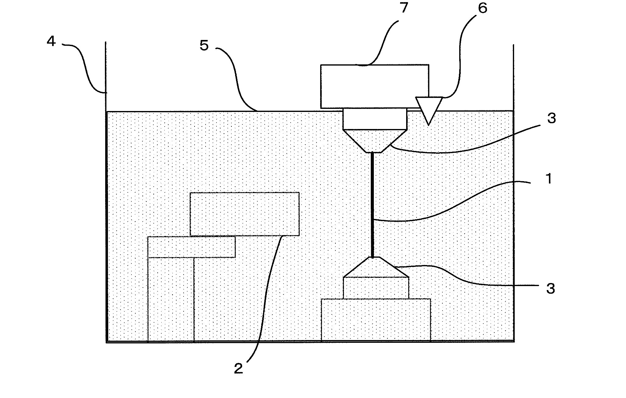
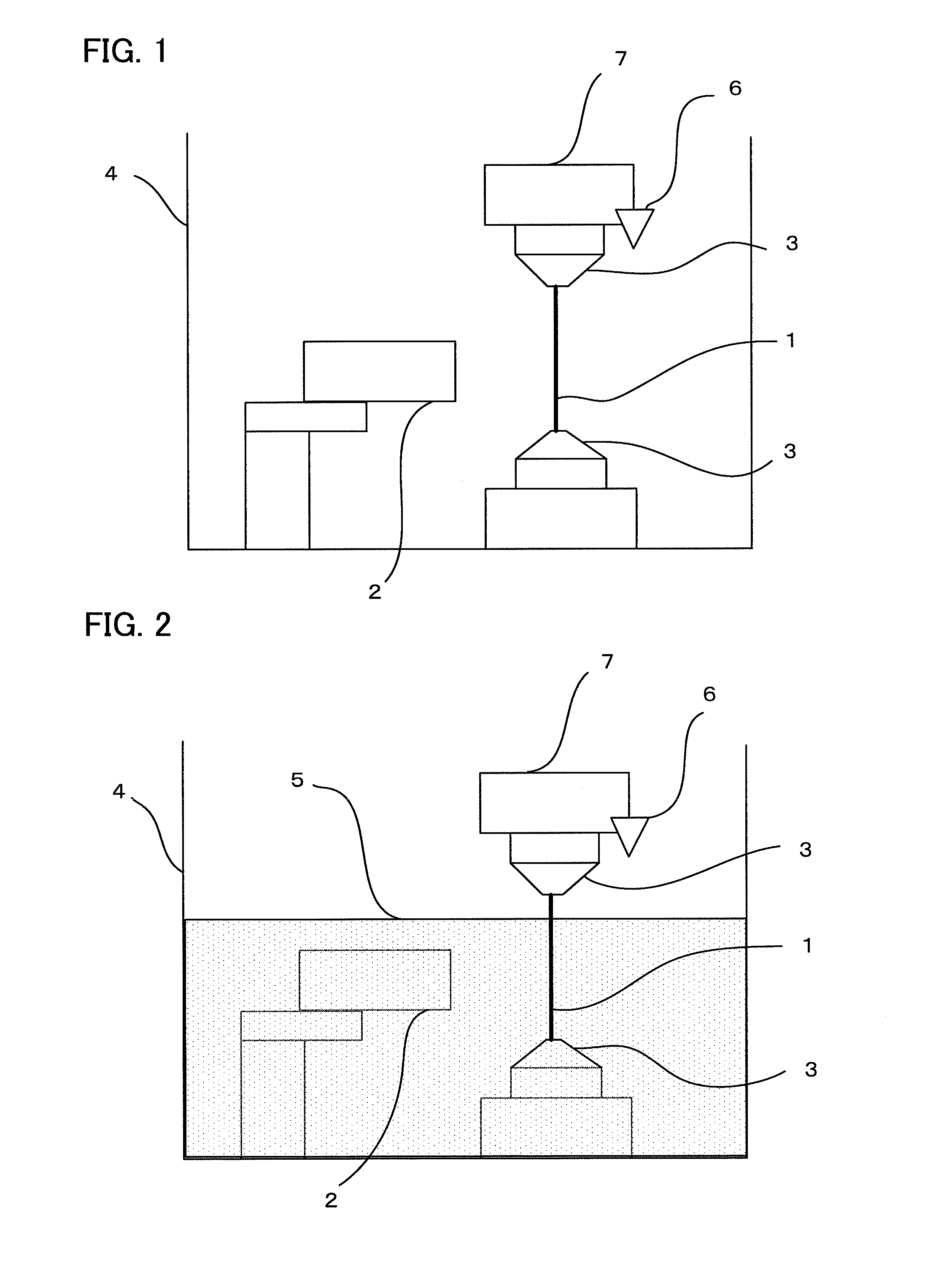
[0035]In machining by a wire electric discharge machine, as explained above, there are a method of machining a workpiece 2 in a state in which a wire electrode 1 and a workpiece 2 are submerged in a working fluid 5 (submerged machining) and another method of machining a workpiece 2 only by spraying working fluid 5 in a state in which a wire electrode 1 and a workpiece 2 are not submerged in a working fluid 5 (flushing machining). An operator may set any one of those two machining methods that is to be carried out by means of a switch or the like.
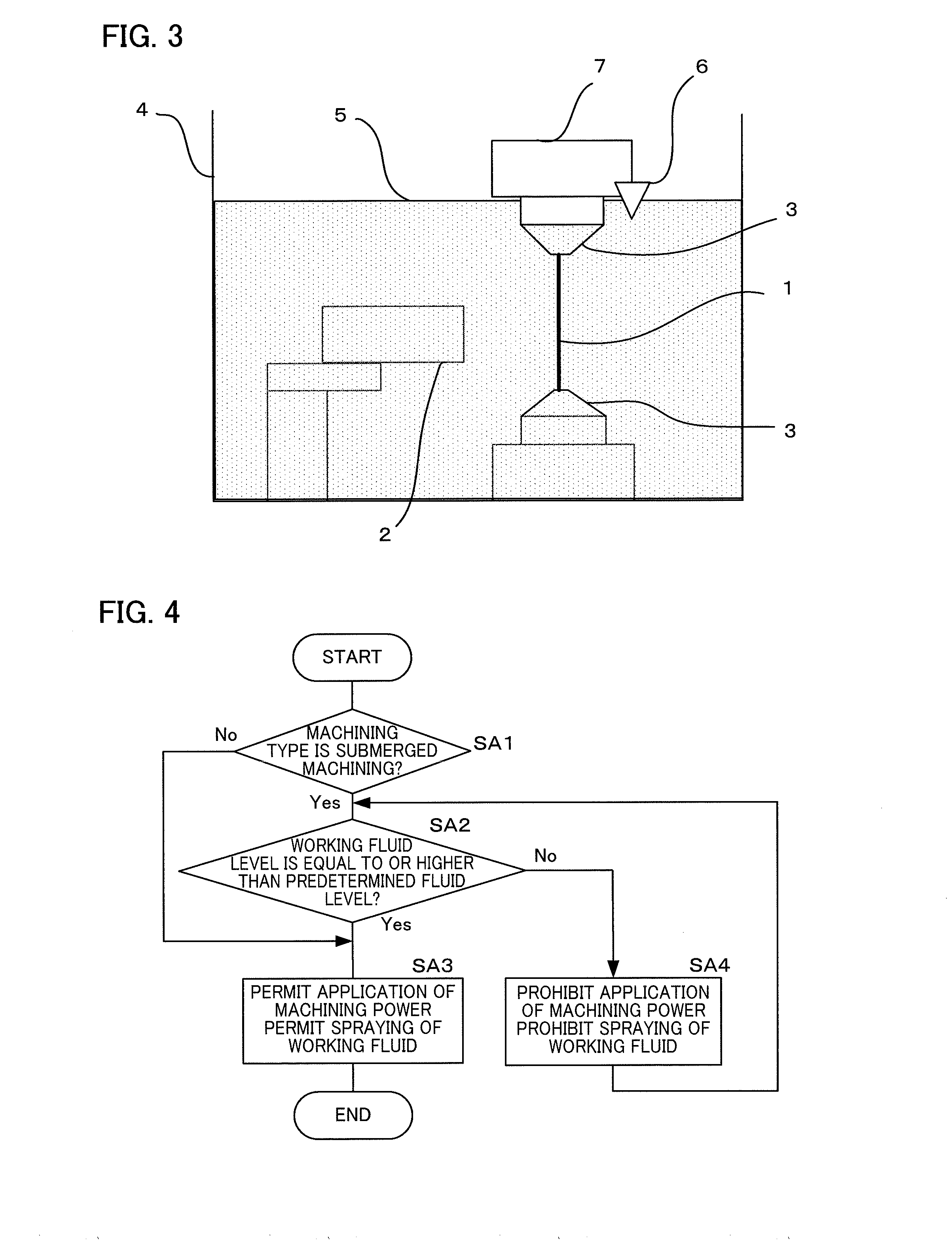
[0036]When the machining is set to the submerged machining, the wire electric discharge machine detects using a fluid level sensor 6 whether a fluid level of the working fluid 5 reaches a predetermined position. If a detection result of the fluid level sensor 6 indicates that the fluid level of the working fluid 5 does not reach the predetermined position, the wire electric discharge machine prohibits a machining power from applied for apply...
second embodiment
[0044]FIG. 6 is a flowchart for explaining state discrimination processing in a work tank of a wire electric discharge machine according to a second embodiment of the present invention. In the state discrimination processing in the work tank according to this embodiment, a function for displaying a warning when an instruction of application of machining power or an instruction of spraying of the working fluid 5 is issued if a fluid level of the working fluid 5 is lower than a predetermined fluid level is added to the state discrimination processing in the work tank according to the first embodiment. In the following explanation, the flowchart is explained step by step.[0045](Step SB1) It is determined whether a machining type of machining by a wire electric discharge machine is the submerged machining or not. If the machining type is the submerged machining (YES), the processing proceeds to step SB2. If the machining type is a machining other than the submerged machining, such as th...
third embodiment
[0051]FIG. 7 is a flowchart for explaining state discrimination processing in a work tank of a wire electric discharge machine according to a third embodiment of the present invention. In the state discrimination processing in the work tank according to this embodiment, a function for automatically supplying working fluid 5 when an instruction of application of machining power or an instruction of spraying of the working fluid 5 is issued if a fluid level of the working fluid 5 is lower than a predetermined fluid level is added to the state discrimination processing in the work tank according to the first embodiment. In the following explanation, the flowchart is explained step by step.[0052](Step SC1) It is determined whether a machining type of machining by a wire electric discharge machine is the submerged machining or not. If the machining type is the submerged machining (YES), the processing proceeds to step SC2. If the machining type is a machining other than the submerged mac...
PUM
| Property | Measurement | Unit |
|---|---|---|
| Electric potential / voltage | aaaaa | aaaaa |
| Level | aaaaa | aaaaa |
Abstract
Description
Claims
Application Information