
Apparatus and method for manufacturing of containers

a technology for containers and accessories, applied in the field of accessories and containers manufacturing, can solve the problems of increasing production, increasing production, and increasing the number of weldable layers, and achieving the effects of reducing acceleration and deceleration forces, reducing transportation speed of containers, and increasing production efficiency

Active Publication Date: 2014-09-25
GPI SYST AB
View PDF22 Cites 10 Cited by
  • Summary
  • Abstract
  • Description
  • Claims
  • Application Information

AI Technical Summary

Benefits of technology

The inventive apparatus has two main benefits. Firstly, it allows for simultaneous handling of containers during welding, which increases the production rate without compromising the quality of the welds. Secondly, it reduces the speed of transportation and acceleration / deceleration forces during intermittent handling, leading to higher output.

Problems solved by technology

Also the body blank may be welded together as to form the cylindrical container body, but welding of the end closure is usually a more complex process step.
An important issue in this context is the production rate, i.e. the number of containers per, say, minute that can be manufactured.
A problem when trying to increase the production rate of conventional equipment is that the weldable layer does not get sufficient time to heat up, cool and harden before the containers are removed and transported away from the welding unit.
This often results in a damaged and leaking joint.
Various heating and cooling devices, as well as different weldable material, have been proposed for carrying out the step of fastening the end closures more quickly but their performance has not been satisfactory.

Method used


Image

  • Apparatus and method for manufacturing of containers
  • Apparatus and method for manufacturing of containers
  • Apparatus and method for manufacturing of containers

Examples


Embodiment Construction

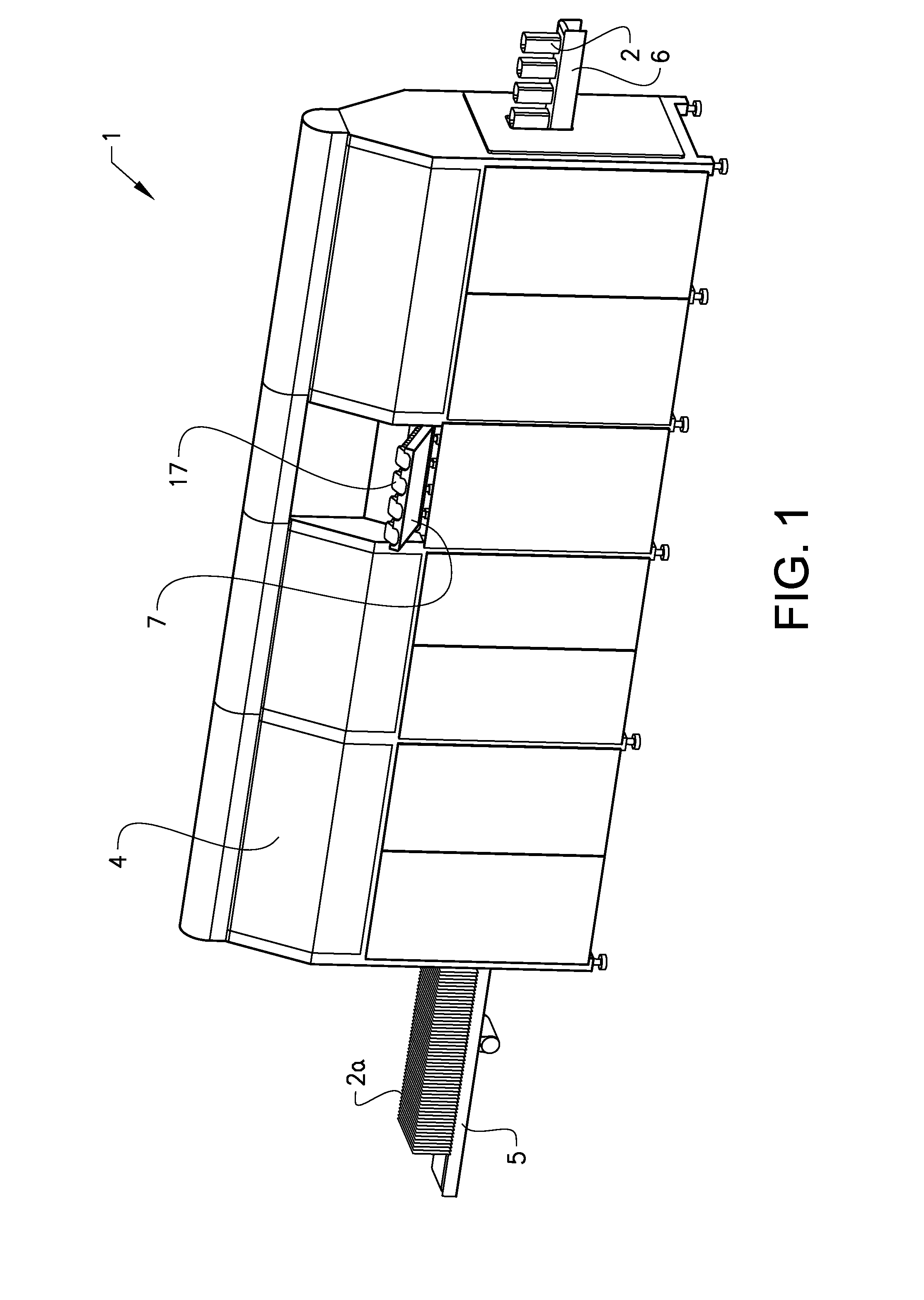
[0035]FIG. 1 shows, in a perspective view, a preferred embodiment of an inventive apparatus 1 for manufacturing of containers 2 from blanks 2a of a cardboard based material. A housing 4 is arranged to surround the apparatus 1. An inlet conveyor 5 feeds vertically positioned body blanks 2a to the apparatus 1 and an outlet conveyor 6 feeds containers 2 away from the apparatus 1. An end closure supply unit 7 with end closures 17 can be seen in FIG. 1.

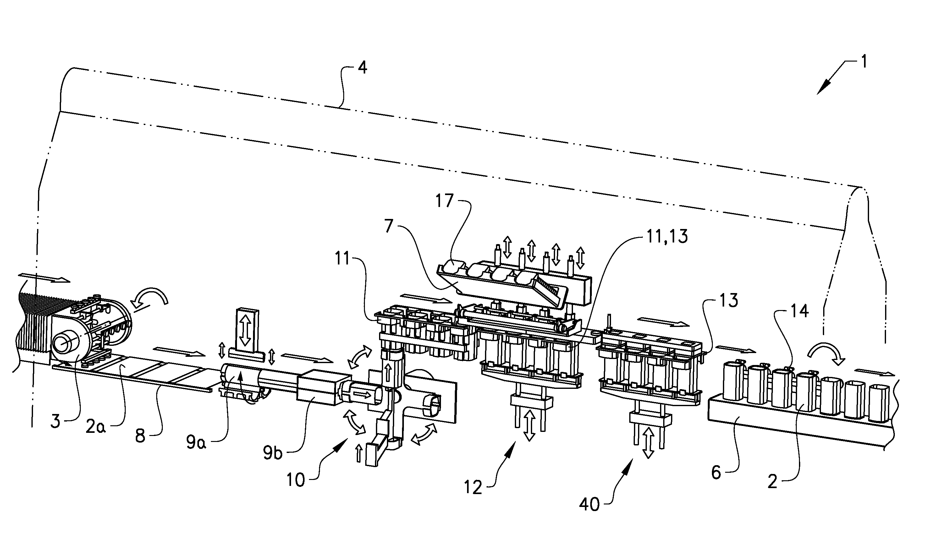
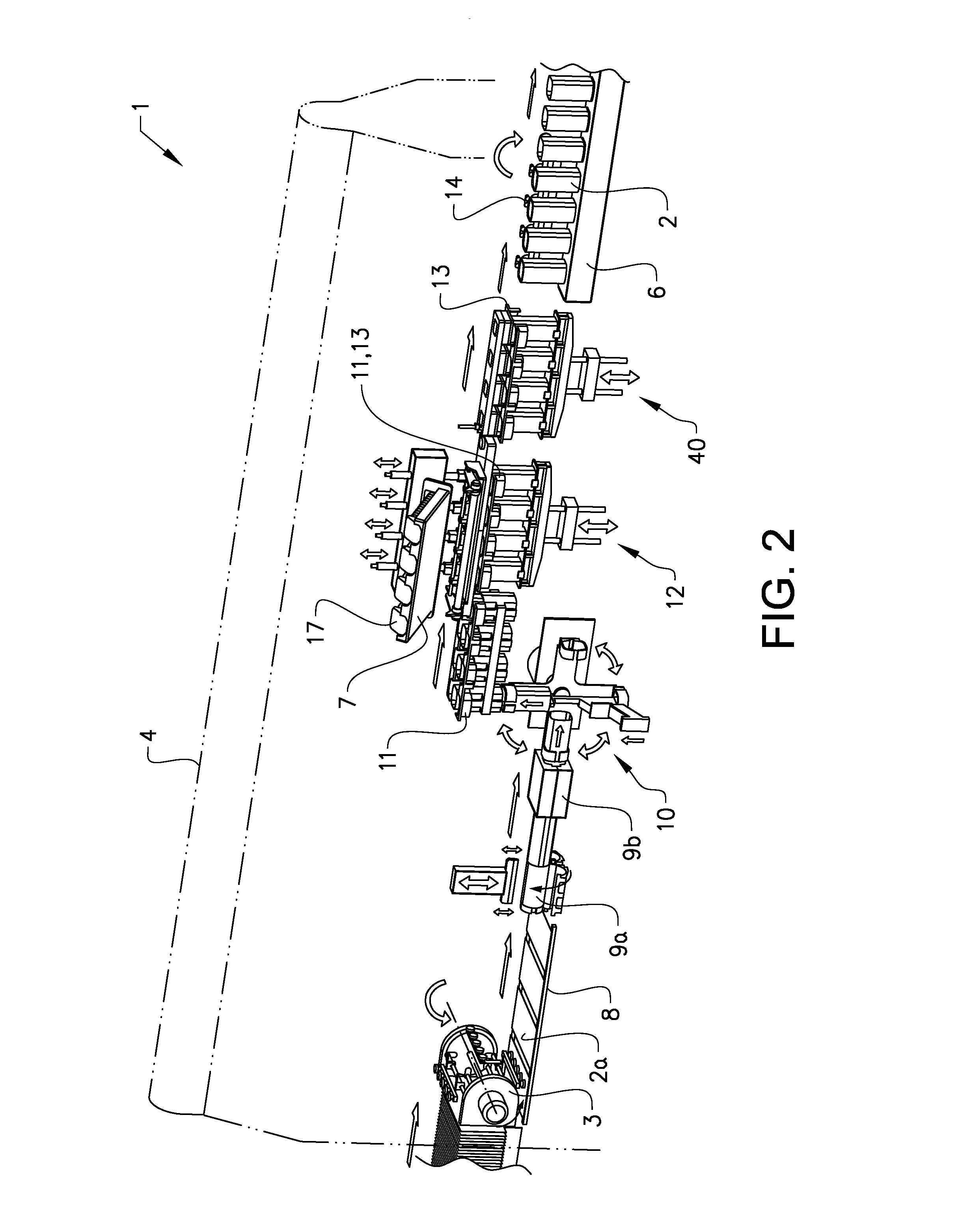
[0036]FIG. 2 shows parts of the inside of the apparatus 1 shown in FIG. 1. From left to right in FIG. 2, i.e. from inlet side to outlet side of the apparatus 1. it is shown a blank picker 3, a body blank 2a placed horizontally onto a conveyor 8, a container body welding station 9a, a body shaping station 9b, a container body transferring and positioning arrangement 10, a first movable gripping arrangement 11, end closures 17 arranged in the end closure supply unit 7, a welding unit 12, a second movable gripping arrangement 13, a container ...


PUM

PropertyMeasurementUnit
temperatureaaaaaaaaaa
angleaaaaaaaaaa
distanceaaaaaaaaaa

Abstract

The invention concerns an apparatus for manufacturing of containers from blanks of a cardboard based material, said apparatus comprising: a container body forming unit configured to form a cylindrical container body from a substantially plane blank of a multilayer material comprising at least a supporting cardboard layer and a weldable layer; a welding unit configured to fasten an end closure to the container body, said welding unit comprising an inductive welding energy generator for melting of the weldable layer; and transporting means configured to transport a flow of body blanks to the container body forming unit, to transport a flow of container bodies from the container body forming unit to the welding unit, and to transport a flow of container bodies provided with end closures from the welding unit. The invention is characterized in that the transporting means comprises: a first movable gripping arrangement configured to grip at least two container bodies and move these container bodies simultaneously to the welding unit; and a transferring and positioning arrangement configured to transfer container bodies from the container body forming unit to the first movable gripping arrangement and to position the container bodies in a controlled manner to ensure that the first movable gripping arrangement can grip the at least two container bodies properly, wherein the welding unit is configured to simultaneously fasten an end closure to each of the at least two container bodies. The invention also concerns a method for operating an apparatus of the above type.

Description

TECHNICAL FIELD[0001]This invention relates to an apparatus and method for manufacturing of containers from blanks of a cardboard based material. In particular, the invention relates to an apparatus and method where an end closure is fastened to a container body by inductive heating for melting of a weldable layer that forms part of the container body and / or the end closure.BACKGROUND OF THE INVENTION[0002]Equipment for manufacturing of containers from blanks of a cardboard based material is described in e.g. EP0074343. Such equipment normally includes a container body forming unit where a cylindrical container body is formed from a substantially plane blank of a multilayer material comprising at least a supporting cardboard layer and a weldable, plastic layer. In a welding unit, an end closure, a bottom, is applied to the inside of the container body by inducing welding energy and melting the weldable layer. Such a welded joint is well known to be capable of being gas tight. After ...

Claims


Application Information

Patent Timeline
Patent Type & Authority Applications(United States)
IPC IPC(8): B31B17/74B31B50/04
CPCB31B17/74B31B2201/922B31B2201/22B31B2201/6026B29C65/3656B29C65/3684B29C65/7847B29C65/7864B29C65/7867B29C66/1122B29C66/4322B29C66/49B29C66/53462B29C66/5432B29C66/612B29C66/72328B29C66/8322B29C66/8432B29C66/849B29L2031/7162B65B7/2892B65B43/185B65B43/265B65B51/227B31B50/005B31B50/024B31B50/046B31B50/06B31B50/07B31B50/28B31B50/66B31B2105/00B31B2105/0022B31B2110/20B31B50/59B31B50/64B31B50/94B31B70/74
Inventor HAGELQVIST, PER
Owner GPI SYST AB
Learn More