Pressure reducing valve

a technology of pressure reducing valve and seal member, which is applied in the direction of fluid pressure control, process and machine control, instruments, etc., can solve the problems of affecting the sealing ability affecting the sealing performance of the seal member, so as to avoid the damage of the seal member due to abrasion debris, the effect of increasing the frictional resistance of the piston

Active Publication Date: 2014-10-02
HONDA MOTOR CO LTD
View PDF16 Cites 5 Cited by
  • Summary
  • Abstract
  • Description
  • Claims
  • Application Information

AI Technical Summary

Benefits of technology

[0012]It is a general object of the present invention to provide a pressure reducing valve in which the displacement speed of a piston can be ensured.
[0020]In the structure described above, preferably, the rings are disposed on both ends in a direction of displacement of an area that lies within the side wall of the piston and which is held in sliding contact with the inner wall of the body. In this case, because both ends in the direction of displacement of the sliding contact area of the piston are supported, it is unlikely that tilting of the piston will occur. Accordingly, a condition in which a portion of the side wall of the piston or the rings presses against the inner wall of the body, and an increase in sliding resistance of the piston as a result thereof, can be avoided.

Problems solved by technology

Further, it is common that the piston and the cover are constituted from metal materials, and thus during sliding contact therebetween, the piston or the body is subjected to wear and abrasion.
As a result, abrasion debris (metal powder) is produced.
If such abrasion debris enters between the o-rings and the inner circumferential wall of the cover, there is a concern that, upon displacement of the piston, the o-rings, which are made of a material that is softer and more flexible compared to the cover, will become scratched and damaged.
When such a condition occurs, it is conceivable that the sealing capability of the o-rings deteriorates.

Method used


Image

  • Pressure reducing valve
  • Pressure reducing valve
  • Pressure reducing valve

Examples


Embodiment Construction

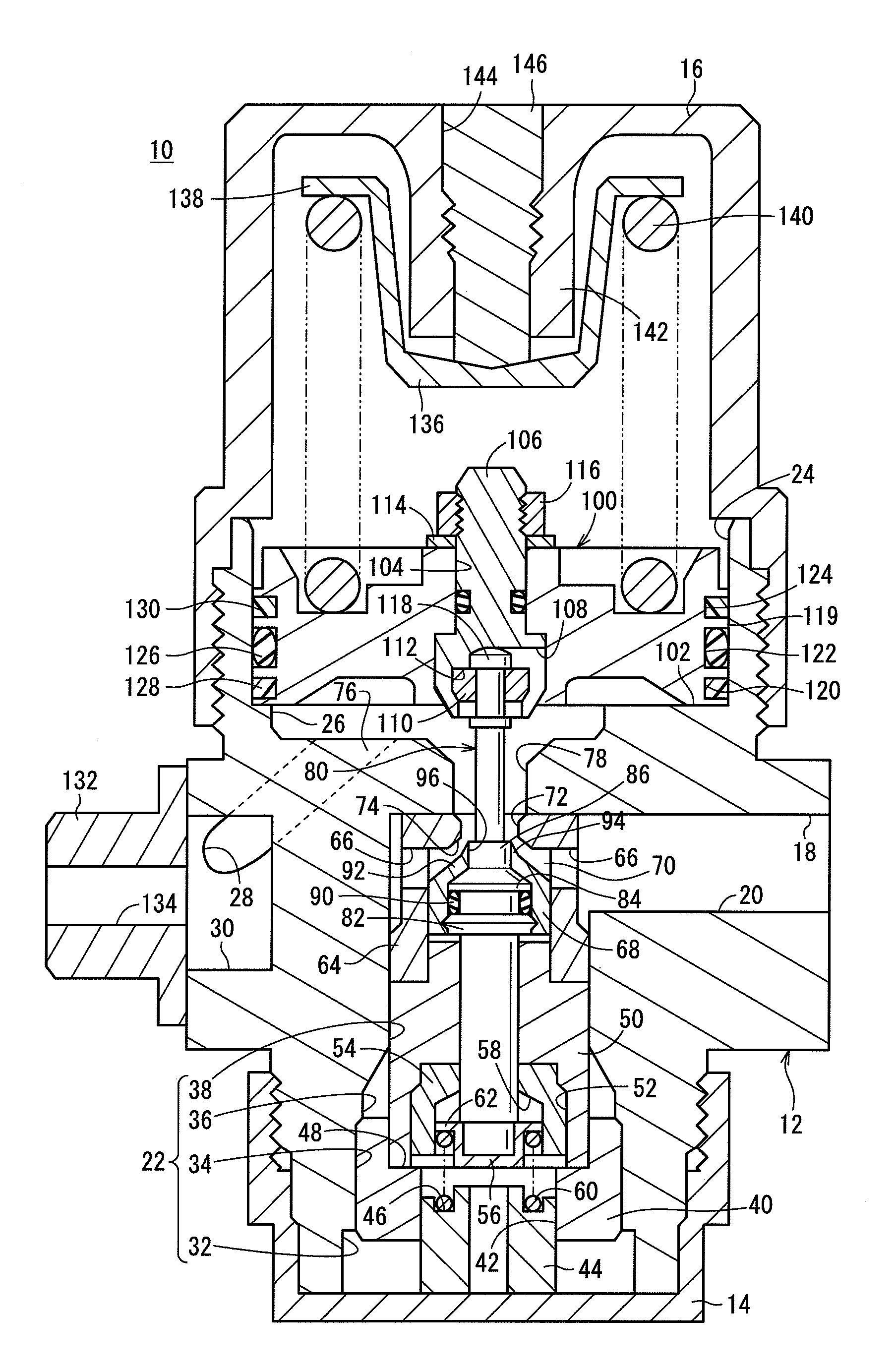
[0029]A pressure reducing valve according to an embodiment of the present invention will be described in detail below with reference to the accompanying drawings. The terms “lower”, “upper”, “left”, and “right” as well as other words representing directions will be used to indicate corresponding directions in FIG. 1. Moreover, the terms “lower end” and “upper end” as well as other phrases indicative of directions will be used to refer to objects positioned in such corresponding directions in FIG. 1.

[0030]FIG. 1 is a longitudinal cross-sectional view of a pressure reducing valve 10 according to an embodiment of the present invention, the pressure reducing valve 10 being shown in an open state. As shown in FIG. 1, the pressure reducing valve 10 includes a body 12 that opens upwardly and downwardly, a lower cover 14 mounted on a lower end of the body 12, and an upper cover 16 mounted on an upper end of the body 12.

[0031]The body 12 has an inlet port 18 for introducing a fluid into the ...


PUM


Abstract

A pressure reducing valve has a seal member, which is mounted on a side wall of a piston. The seal member is arranged between a first ring and a second ring. Consequently, depending on the direction of displacement of the piston, the first ring or the second ring is positioned on one of a displacement direction upstream side or a displacement direction downstream side of the seal member. The first ring and the second ring are made of a resin material, for example a polytetrafluoroethylene resin or a polyetheretherketone resin, having lower coefficient of friction compared with that of the seal member.

Description

CROSS-REFERENCE TO RELATED APPLICATION[0001]This application is based upon and claims the benefit of priority from Japanese Patent Application No. 2013-065434 filed on Mar. 27, 2013, the contents of which are incorporated herein by reference.BACKGROUND OF THE INVENTION[0002]1. Field of the Invention[0003]The present invention relates to a pressure reducing valve, which includes a piston that is displaceable depending on a pressure in a decompression chamber.[0004]2. Description of the Related Art[0005]As well known in the art, pressure reducing valves function to reduce the pressure of a high-pressure fluid to a given pressure. As one detailed example thereof, a pressure reducing valve of this type is disclosed in Japanese Laid-Open Patent Publication No. 2009-157692.[0006]The pressure reducing valve disclosed in Japanese Laid-Open Patent Publication No. 2009-157692 includes a substantially rod-shaped piston disposed at an upward end of a valve element, a first helical spring, which...

Claims


Application Information

Patent Timeline
Patent Type & Authority Applications(United States)
IPC IPC(8): G05D16/10
CPCG05D16/106G05D16/107Y10T137/7793Y10T137/7825
Inventor IITAKA, SATOSHIMIURA, TANEAKITAKAKU, KOICHIOZAKI, HIROYASU
Owner HONDA MOTOR CO LTD
Why Eureka
Try Eureka