Sheet manufacturing apparatus

Active Publication Date: 2014-10-02
SEIKO EPSON CORP
View PDF1 Cites 25 Cited by
  • Summary
  • Abstract
  • Description
  • Claims
  • Application Information

AI Technical Summary

Benefits of technology

[0024]With this configuration, the moisture amount of the defibrated material is easily

Problems solved by technology

Wet type sheet manufacturing apparatuses are not suitable to a small scale office because the wet type sheet manufacturing apparatuses use large amount of water.
However, even if the sheet manufacturing apparatuses use same sheet material and perform pressurizing and heating in same way, it is possible that the sheet lacks st

Method used


Image

  • Sheet manufacturing apparatus
  • Sheet manufacturing apparatus
  • Sheet manufacturing apparatus

Examples


Example

First Embodiment

[0039]First, a configuration of a sheet manufacturing apparatus is described. The sheet manufacturing apparatus is based on an art in recycling defibration object, such as used paper (with stock material Pu or pulp sheets) to new sheets. The apparatus controls quantity of heat to be added to defibrated material on the basis of moisture amount information of the defibrated material. A stock material of the defibration object is supplied to the sheet manufacturing apparatus in the present embodiment. An example of the stock material is used paper in A4 size which is typically used in the office. It will be specifically described hereinafter.

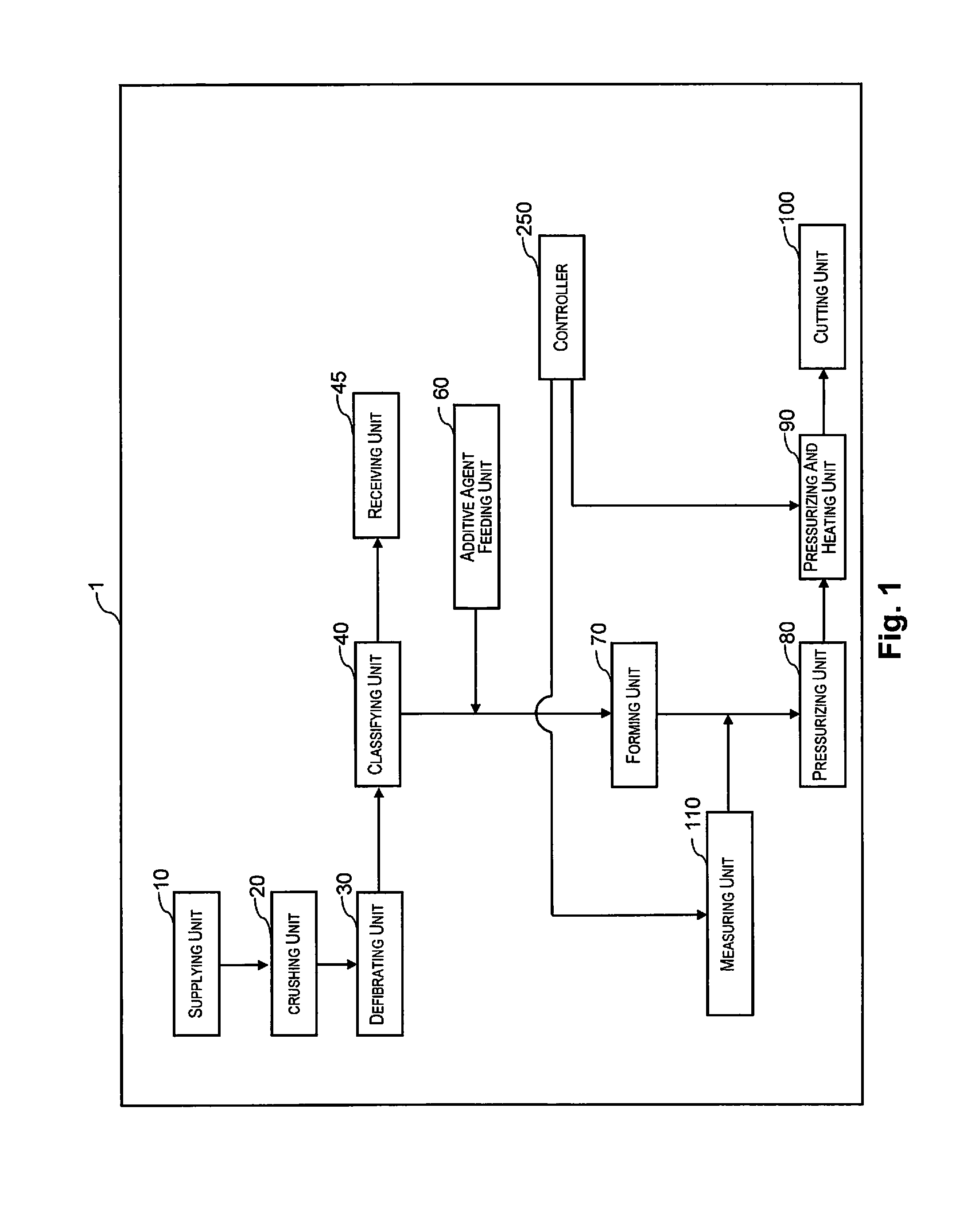
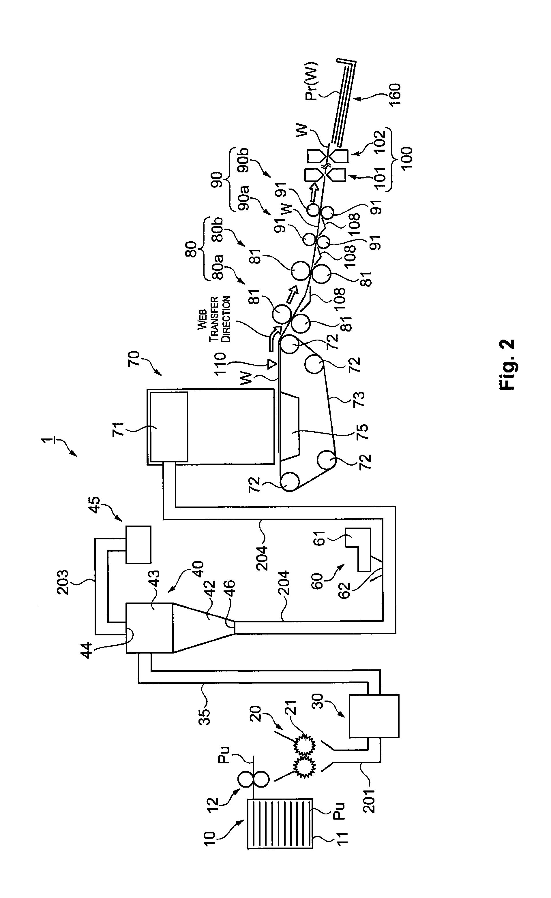
[0040]FIGS. 1 and 2 are the schematic views which show configurations of the sheet manufacturing apparatus. As shown in FIGS. 1 and 2, the sheet manufacturing apparatus 1 includes a supplying unit 10, a crushing unit 20, a defibrating unit 30, a classifying unit 40, a receiving unit 45, an additive feeding unit 60, a forming unit 70...

Example

Second Embodiment

[0073]First, a configuration of a sheet manufacturing apparatus is described.

[0074]FIGS. 4 and 5 are schematic views showing the configuration of the sheet manufacturing apparatus. As shown in FIGS. 4 and 5, the sheet manufacturing apparatus 1a includes the supplying unit 10, the crushing unit 20, the defibrating unit 30, the classifying unit 40, the receiving unit 45, the additive feeding unit 60, the forming unit 70, the pressurizing unit 80, the pressurizing and heating unit 90, and the cutting unit 100. Further, the sheet manufacturing apparatus 1a includes the measuring unit 110 which acquires the moisture amount information of the defibration object. The measuring unit 110 of the present embodiment is configured on the supplying unit 10. And the sheet manufacturing apparatus 1a includes the controller 250 which controls theses portions.

[0075]The measuring unit 110 of the present embodiment is different from one in the first embodiment. Other than that, each po...

Example

Third Embodiment

[0088]First, a configuration of a sheet manufacturing apparatus is described. The sheet manufacturing apparatus of the present embodiment has a function of controlling the moisture amount of the defibrated material on the basis of the moisture amount information of the defibrated material. Further, the sheet manufacturing apparatus has a function of controlling the moisture amount of the defibrated material to be constant on the basis of the moisture amount information of the defibrated material.

[0089]FIGS. 7 and 8 are schematic views showing the sheet manufacturing apparatus of the present embodiment. As shown in FIGS. 7 and 8, the sheet manufacturing apparatus 1b includes the supplying unit 10, the crushing unit 20, the defibrating unit 30, the classifying unit 40, the receiving unit 45, the additive feeding unit 60, the forming unit 70, the pressurizing unit 80, the pressurizing and heating unit 90, and the cutting unit 100. Further, the sheet manufacturing appara...


PUM

PropertyMeasurementUnit
Temperatureaaaaaaaaaa

Abstract

A sheet manufacturing apparatus includes a defibrating unit configured to defibrate a defibration object including at least a fiber, in air. The sheet manufacturing apparatus forms a sheet by adding quantity of heat to a defibrated material defibrated at the defibrating unit. The sheet manufacturing apparatus includes a measuring unit configured to acquire moisture amount information of the defibrated material or the defibration object, and a controller configured to control the quantity of heat to be added to the defibrated material on the basis of the moisture amount information.

Description

CROSS-REFERENCE TO RELATED APPLICATIONS[0001]This application claims priority to Japanese Patent Application No. 2013-065795 filed on Mar. 27, 2013 and Japanese Patent Application No. 2014-025120 filed on Feb. 13, 2014. The entire disclosure of Japanese Patent Application Nos. 2013-065795 and 2014-025120 is hereby incorporated herein by reference.BACKGROUND[0002]1. Technical Field[0003]The present invention relates to a sheet manufacturing apparatus.[0004]2. Related Art[0005]There has been a demand that used paper is processed in office in view of confidentiality because the used paper abandoned in the office may contain confidential material. Wet type sheet manufacturing apparatuses are not suitable to a small scale office because the wet type sheet manufacturing apparatuses use large amount of water. Dry type sheet manufacturing apparatuses which have simple structures have been suggested (for example, please see Japanese Unexamined Laid Open Patent Publication No. 2012-144819).[0...

Claims


Application Information

Patent Timeline
IPC IPC(8): D21H25/04
CPCD21H25/04D21B1/06D21B1/08D21F9/02D21G9/0036Y02W30/64
Inventor NAGAI, YOSHIYUKISEKI, SHUNICHI
Owner SEIKO EPSON CORP
Why Eureka
Try Eureka