Accumulated power consumption sensor: application in smart batteries systems

a technology of accumulated power consumption and smart batteries, applied in the direction of passive battery identification, charge equalisation circuit, instruments, etc., can solve the problems of small charge, no longer useful, and the inability to recharge rechargeable batteries limitless times, and achieve the effect of estimating the remaining life cycle of rechargeable battery cells

Active Publication Date: 2014-10-02
STMICROELECTRONICS INT NV
View PDF2 Cites 11 Cited by
  • Summary
  • Abstract
  • Description
  • Claims
  • Application Information

AI Technical Summary

Benefits of technology

[0008]In one embodiment when the smart battery provides power to the portable electronic device, the battery also provides power to the battery life sensor. Thus, each time the smart battery provides power to the portable electronic device, the battery life sensor receives an electrical signal indicating that the rechargeable battery cell is discharging. The battery life sensor can provide an indication of the total accumulated power discharged from the rechargeable battery cell during the life of the rechargeable battery cell. For a battery that has discharged so much power that the end of its useful life cycle is approaching, the battery life sensor can provide an indication that the rechargeable battery cell needs to be replaced.
[0009]In one embodiment the battery life sensor includes an adjustable resistor whose resi

Problems solved by technology

However, rechargeable batteries cannot be recharged a limitless number of times. After a rechargeable battery goes through many cycles of discharging and charging, the rechargeable battery begins to hold less charge upon being recharged.
As the battery co

Method used


Image

  • Accumulated power consumption sensor: application in smart batteries systems
  • Accumulated power consumption sensor: application in smart batteries systems
  • Accumulated power consumption sensor: application in smart batteries systems

Examples


Embodiment Construction

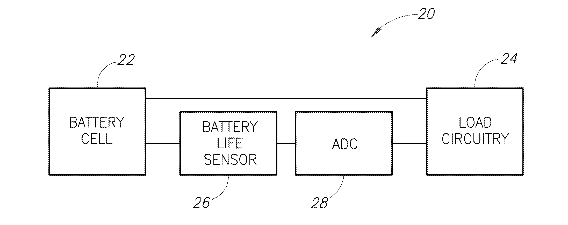
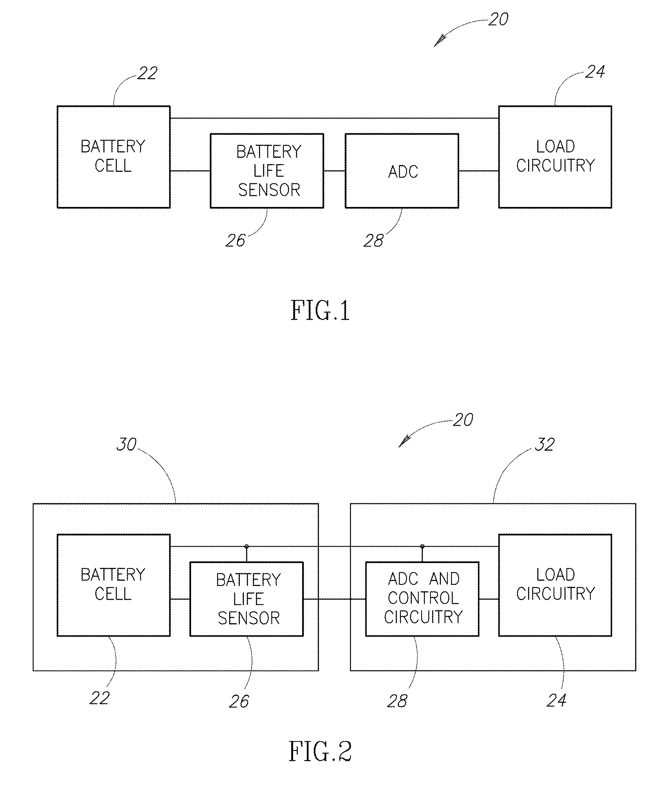
[0023]FIG. 1 is a block diagram of an electronic device 20 according to one embodiment. The electronic device 20 includes a battery cell 22 coupled to load circuitry 24 and battery life sensor 26. An analog-to-digital converter / controller 28 is coupled to the battery life sensor 26 and the load circuitry 24.

[0024]The battery cell 22 is a rechargeable battery cell. When the electronic device 20 is in use, the battery cell 22 provides power to the load circuitry 24. Current passes from the battery cell 22 through the load circuitry 24. The load circuitry 24 performs its functions using power from the battery cell 22.

[0025]After providing power to the load circuitry 24 for some amount of time, the battery cell 22 is depleted of its charge and must be recharged in order to provide power to the load circuitry 24 again. After the battery cell 22 has been recharged, the battery cell 22 can again provide power to the load circuitry 24. It might be used for a short period and then charged ag...


PUM


Abstract

A device is provided for monitoring the total current discharged from a battery. The device includes a bridge circuit of resistors in which one of the resistors has a resistance which varies according to the current which has passed through it. Whenever the battery passes a current to a load, a small portion of the current is passed through the bridge circuit.

Description

BACKGROUND[0001]1. Technical Field[0002]The present disclosure relates to the field of electronic devices powered by batteries. The present disclosure relates more particularly to the field of monitoring the life of a battery.[0003]2. Description of the Related Art[0004]Batteries are included in nearly every kind of portable electronic device. Most portable electronic devices include rechargeable batteries which, upon being depleted of their charge, can be recharged so that they may be used again.[0005]However, rechargeable batteries cannot be recharged a limitless number of times. After a rechargeable battery goes through many cycles of discharging and charging, the rechargeable battery begins to hold less charge upon being recharged.[0006]As the battery continues to be charged and discharged, eventually the battery holds so small a charge that it is no longer useful. Not only does the battery store less charge, but the maximum voltage between the terminals of the charged battery a...

Claims


Application Information

Patent Timeline
IPC IPC(8): G01R31/36
CPCG01R31/3606G01R31/3679G01R31/3662G01R31/392G01R31/389H02J7/0016H02J7/0036H02J7/00038
Inventor LE NEEL, OLIVIERLEUNG, CALVIN
Owner STMICROELECTRONICS INT NV
Why Eureka
Try Eureka