Display device with touch detecting function and electronic apparatus
a display device and touch detection technology, applied in the field of display devices, can solve problems such as the visual recognition of the mirror
- Summary
- Abstract
- Description
- Claims
- Application Information
AI Technical Summary
Benefits of technology
Problems solved by technology
Method used
Image
Examples
first embodiment
1-1. First Embodiment
[0055]1-1A. Exemplary Configuration
[0056]Exemplary Entire Configuration
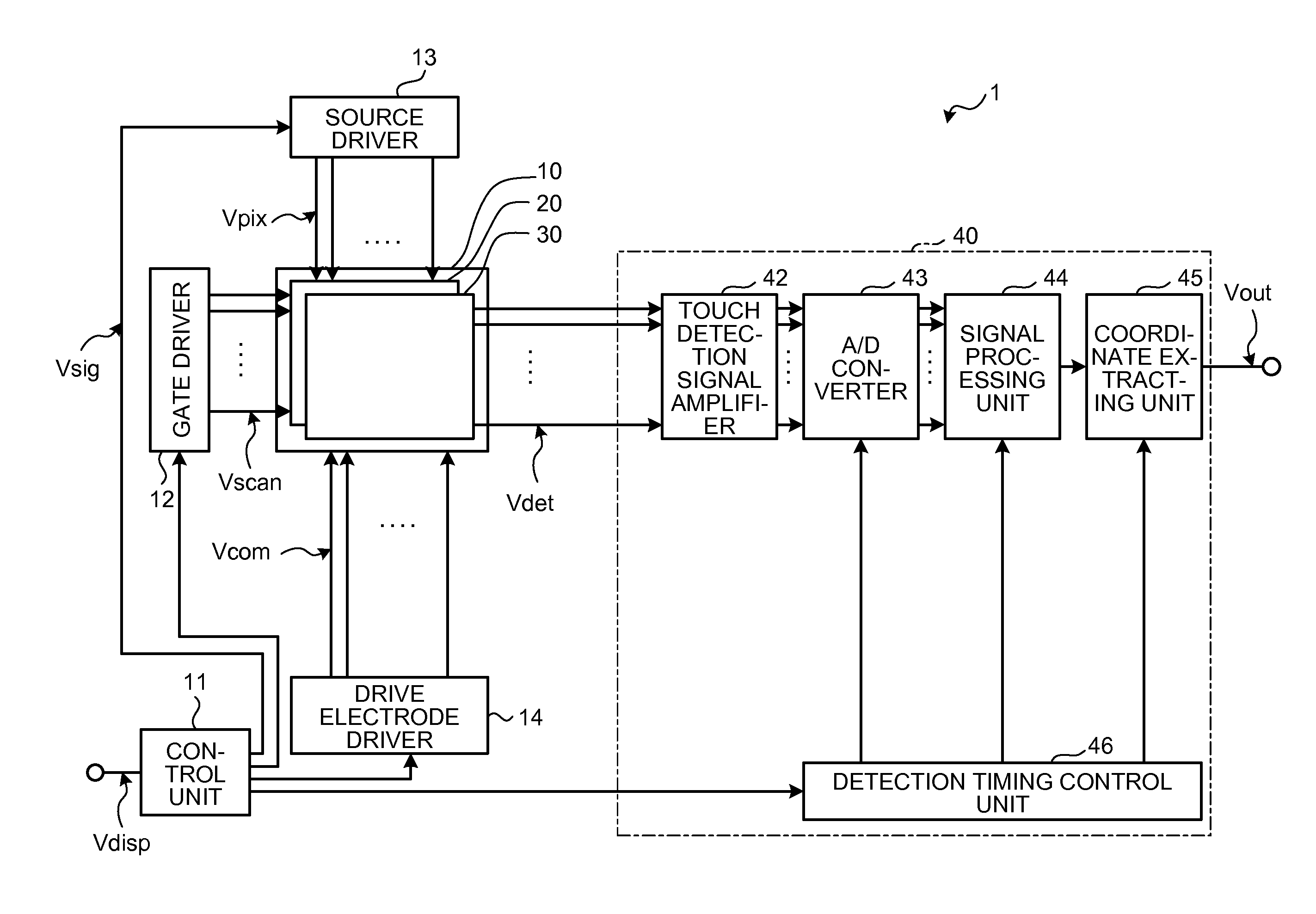
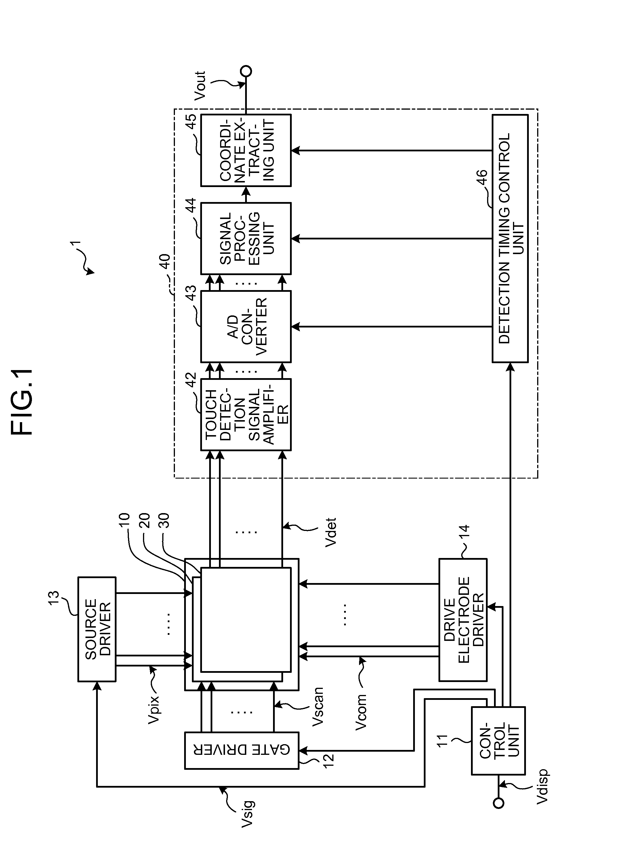
[0057]FIG. 1 is a block diagram of an exemplary configuration of a display device with a touch detecting function according to a first embodiment. A display device 1 with a touch detecting function includes a display unit 10 with a touch detecting function, a control unit 11, a gate driver 12, a source driver 13, a drive electrode driver 14, and a touch detecting unit 40. In the display device 1 with a touch detecting function, the display unit 10 with a touch detecting function has a touch detecting function. The display unit 10 with a touch detecting function is a device in which a liquid-crystal display unit 20 provided with liquid-crystal display elements as display elements is integrated with a capacitive touch detecting device 30. The display unit 10 with a touch detecting function may be a device in which the capacitive touch detecting device 30 is mounted on the liquid-crystal display...
second embodiment
1-2. Second Embodiment
[0233]The following describes a display device 1 with a touch detecting function according to a second embodiment. FIG. 20 is a schematic of arrangement of a touch detection electrode TDL according to the second embodiment. Components similar to those of the first embodiment are denoted by the same reference numerals, and a duplicate explanation thereof will be omitted.
[0234]As illustrated in FIG. 20, the touch detection electrode TDL according to the second embodiment includes a plurality of conductive thin wires ML9, ML10, ML11, and ML12 extending in the direction Da on a plane parallel to a counter substrate 3 in an overhead view. The conductive thin wires ML9, ML10, ML11, and ML12 are zigzag lines or wavy lines bent at bent portions TDC1, TDC2, TDC3, and TDC4. The conductive thin wires ML9, ML10, ML11, and ML12 are made of the same material. The conductive thin wire ML9 and the conductive thin wire ML10 are connected to each other at an end ML9e of the cond...
third embodiment
1-3. Third Embodiment
[0258]FIG. 22 is a sectional view of a schematic sectional structure of the display unit with a touch detecting function according to a third embodiment. In the display device 1 with a touch detecting function according to the embodiments and the modifications, the display unit 10 with a touch detecting function is formed by integrating the liquid-crystal display unit 20 provided with liquid crystals of various types of modes, such as the FFS mode and the IPS mode, and the touch detecting device 30. Instead of this, a display unit 10 with a touch detecting function according to the third embodiment illustrated in FIG. 22 may be formed by integrating liquid crystals of various types of modes, such as a twisted nematic (TN) mode, a vertical alignment (VA) mode, and an electrically controlled birefringence (ECB) mode, and a touch detecting device.
PUM
 Abstract
Description
Claims
Application Information
 - R&D
- Intellectual Property
- Life Sciences
- Materials
- Tech Scout
- Unparalleled Data Quality
- Higher Quality Content
- 60% Fewer Hallucinations
Browse by: Latest US Patents, China's latest patents, Technical Efficacy Thesaurus, Application Domain, Technology Topic, Popular Technical Reports.
© 2025 PatSnap. All rights reserved.Legal|Privacy policy|Modern Slavery Act Transparency Statement|Sitemap|About US| Contact US: help@patsnap.com


