
Image recording device

a recording device and image technology, applied in the direction of printing, inking apparatus, other printing apparatus, etc., can solve the problems of disadvantageous replacement of print head, disadvantageous replacement of substrate that is fixed to the support member together with the print head, and uneconomic configuration described above in which print head and substrate are replaced together, etc., to achieve versatility and work efficiency, reduce the work required for connection work connecting the first substrate, and achieve the effect of versatility

Active Publication Date: 2014-10-02
SEIKO EPSON CORP
View PDF1 Cites 12 Cited by
  • Summary
  • Abstract
  • Description
  • Claims
  • Application Information

AI Technical Summary

Benefits of technology

The invention provides a technique that can make it easier to maintain the substrate that controls the print head and also prevent signal degradation.

Problems solved by technology

However, even though the above advantage is obtained, the print head disadvantageously lacks ease of maintenance.
In other words, because the substrate and the print head are fixed on a common support member, when replacing the print head due to its product life or the like, there are cases in which the substrate that is fixed to the support member together with the print head is disadvantageously replaced as well.
However, the print head and the substrate do not necessarily have to be replaced at the same time; accordingly, the configuration described above in which the print head and the substrate are replaced together is uneconomical.
However, when the substrate is provided separate to the print head, the signal path from the substrate to the print head becomes long and the electric signal is disadvantageously degraded.
As described above, when the substrate is supported together with the print head by a common support member, a decrease in the ease of maintenance disadvantageously occurs, and, on the other hand, when the substrate is provided separate to the print head, degradation of the electric signal occurs.

Method used


Image

  • Image recording device
  • Image recording device
  • Image recording device

Examples


Embodiment Construction

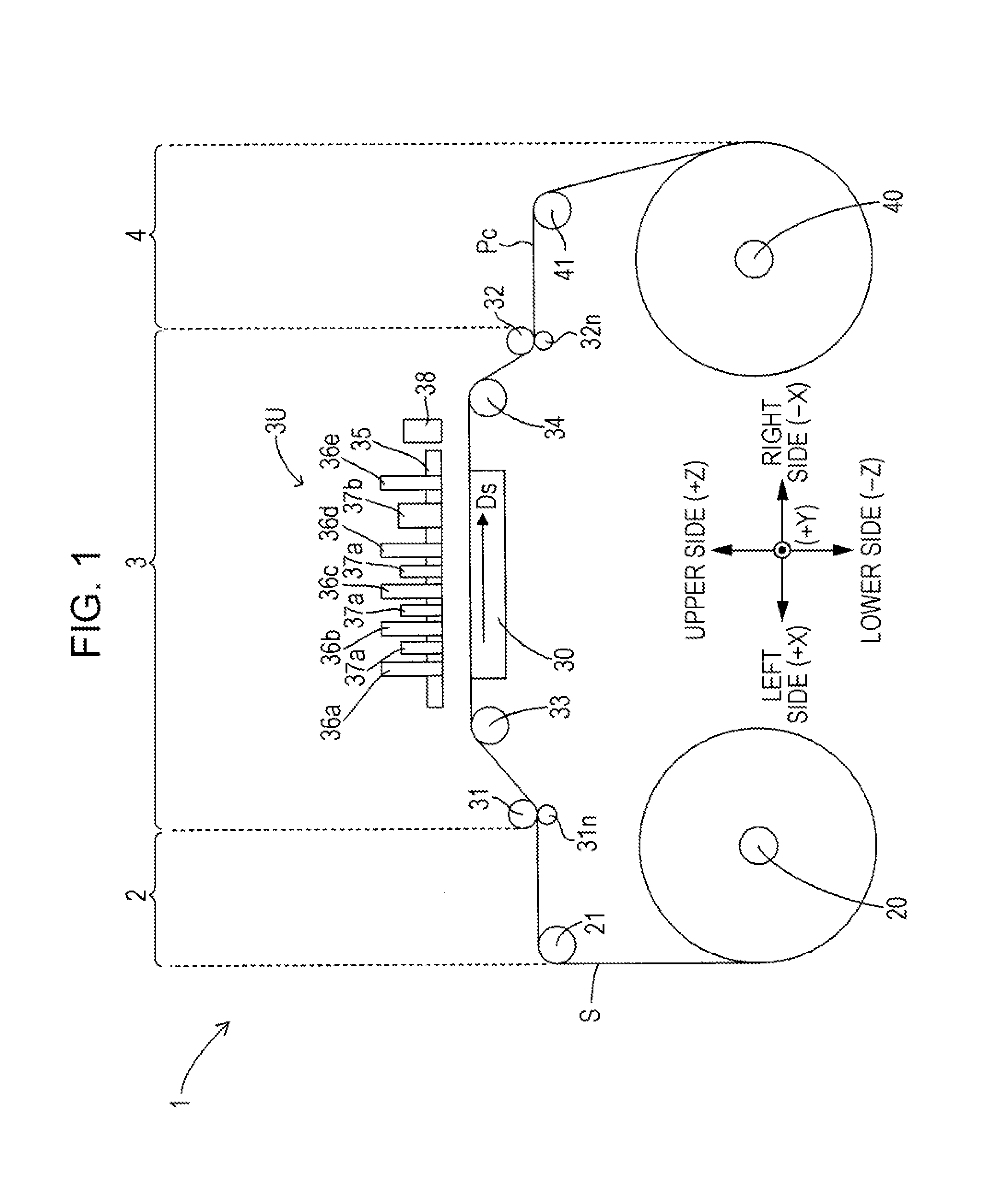
[0028]Exemplary embodiments of an image recording device according to the invention will be described below with reference to the drawings. FIG. 1 is a front view schematically illustrating an exemplary embodiment of the image recording device to which the invention can be applied. Note that in FIG. 1 and other drawings, a three-dimensional, orthogonal coordinate system corresponding to a left-right direction X, a front-rear direction Y, and a vertical direction Z of an image recording device 1 is adopted, as necessary, in order to clearly illustrate the positional relationships of the members of the device.

[0029]As illustrated in FIG. 1, in the image recording device 1, a feeding section 2, a processing section 3, and a winding section 4 are arranged in the left-right direction. The feeding section 2 and the winding section 4 include a feeding shaft 20 and a winding shaft 40, respectively. Furthermore, one of the two ends of a sheet S (web) is wound around the winding section 4 and...


PUM


Abstract

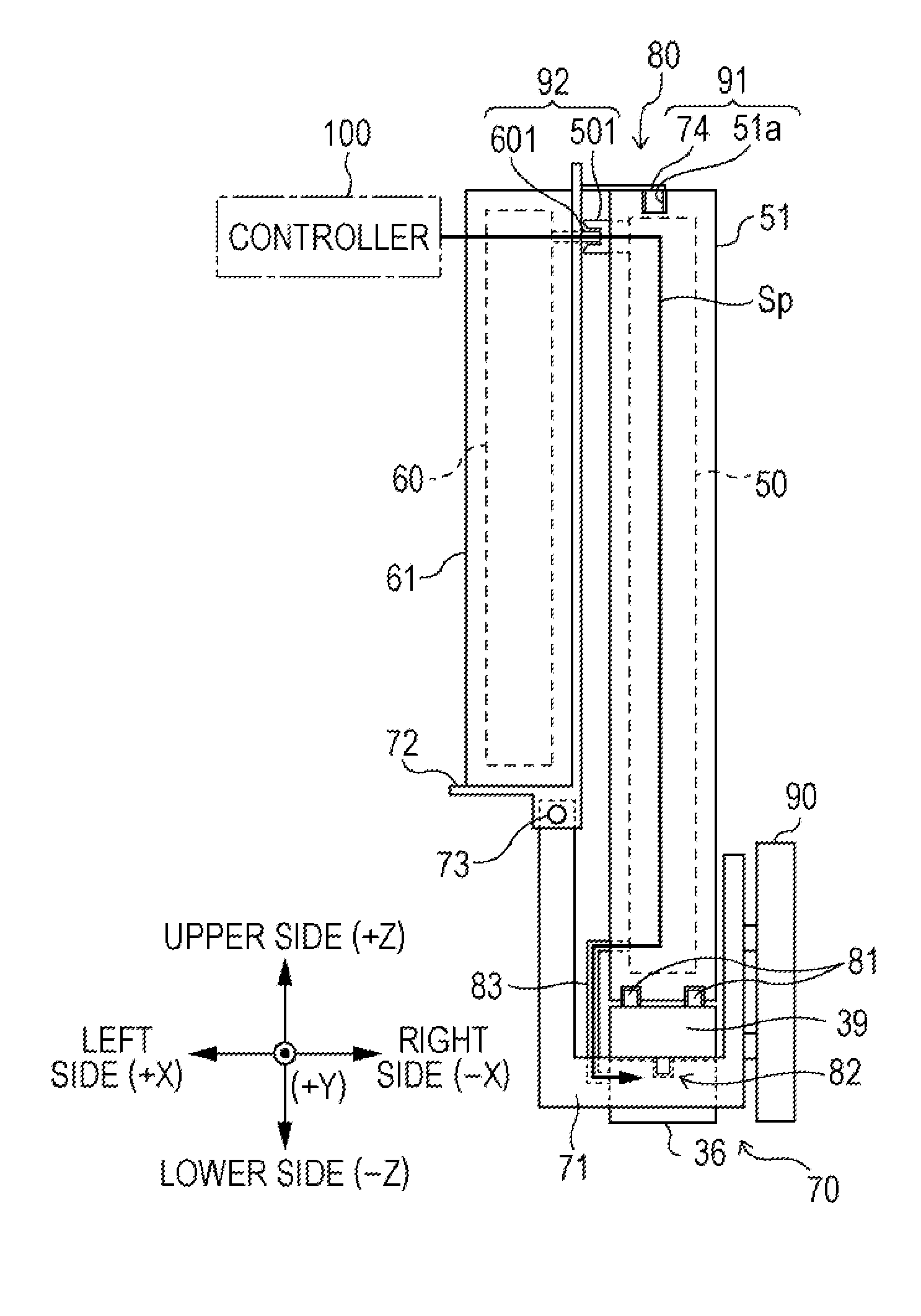
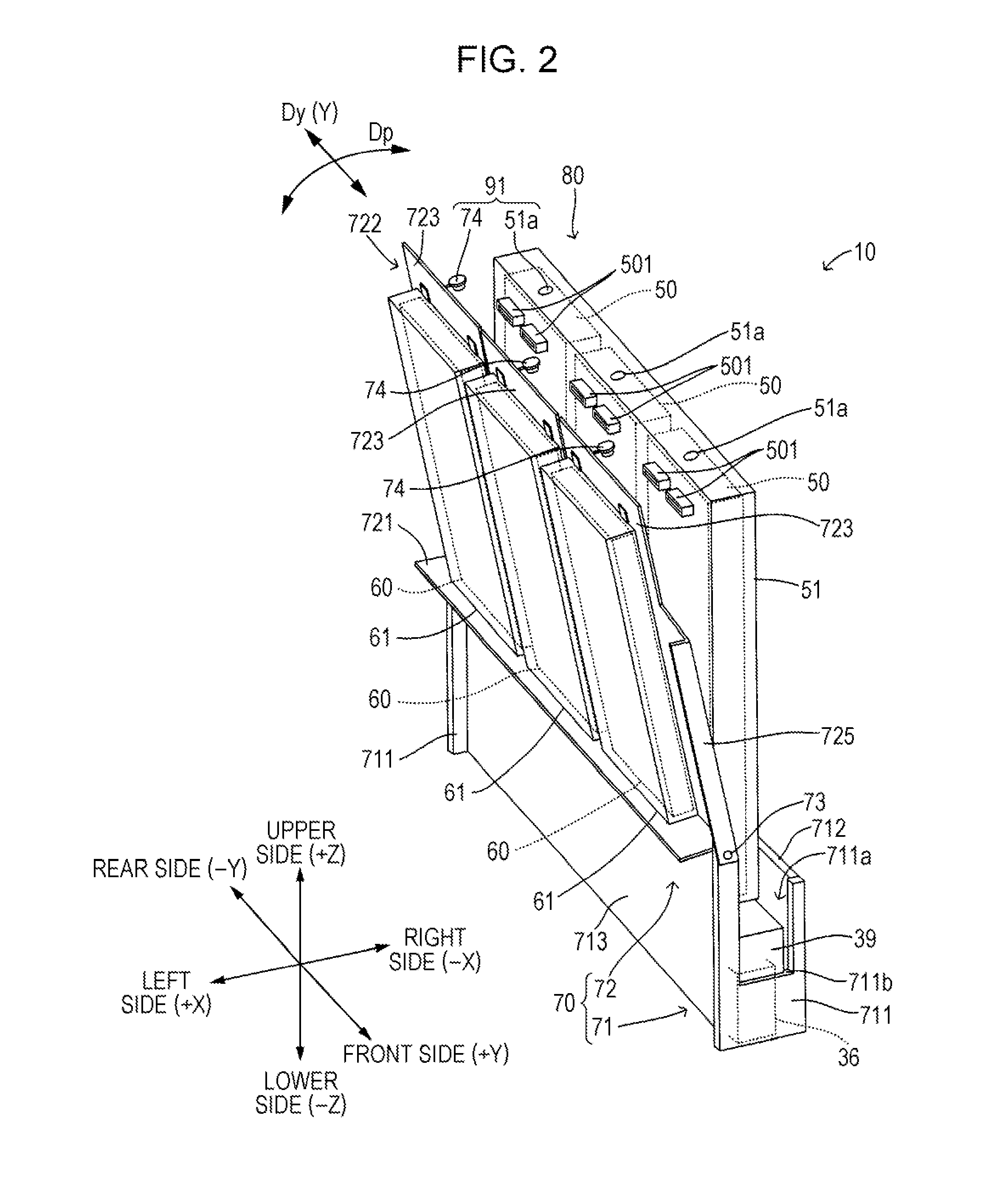
An image recording device includes a head unit having a print head and a first substrate, a second substrate provided separate to the head unit, a support member that supports the head unit and the second substrate while a first positional relationship in which the head unit and the second substrate are close to each other and a second positional relationship in which the head unit and the second substrate are away from each other are changed. Moreover, in the first positional relationship, the head unit and the second substrate are connected to each other to form an electric signal supply path from the second substrate to the head unit, and, conversely, in the second positional relationship, the connection between the head unit and the second substrate is released such that the head unit is dismountable from the support member.

Description

BACKGROUND[0001]1. Technical Field[0002]The present invention relates to a technique for appropriately configuring a circuit substrate that is used to control a print head.[0003]2. Related Art[0004]Hitherto, image recording devices such as ink jet printers that perform image recording by ejecting a liquid from a print head onto a recording medium are provided with an electric circuit that is used to control the print head. In particular, in JP-A-2009-285840, a circuit substrate, on which a drive circuit serving as the above electric circuit is mounted, and a print head are integrally formed and fixed on a common support member.[0005]As described above, when the substrate, which is needed to control the print head, and the print head are fixed on a common support member, the substrate and the print head can be arranged relatively close to each other. Accordingly, a signal path from the substrate to the print head becomes shorter and an advantage is obtained in that degradation of ele...

Claims


Application Information

Patent Timeline
Patent Type & Authority Applications(United States)
IPC IPC(8): B41J2/07
CPCB41J2/07B41J2/14B41J2002/14362B41J2202/20B41J2/17526B41J2/1752B41J2/35B41J2/14072B41J2/155
Inventor WANIBE, AKIHISANAKAYAMA, TERUOKITAZAWA, KOJITSUYUKI, MASAHIKO
Owner SEIKO EPSON CORP
Learn More