Recording apparatus

a recording device and recording medium technology, applied in the field of recording devices, can solve the problems of further significant problems, reduced recording quality, and increased curling problems, and achieve the effect of effective strengthening the flexibility of the recording medium

Active Publication Date: 2014-10-02
SEIKO EPSON CORP
View PDF4 Cites 11 Cited by
  • Summary
  • Abstract
  • Description
  • Claims
  • Application Information

AI Technical Summary

Benefits of technology

[0051]According to the recording apparatus, the flexibility of the recording medium can be effectively strengthen

Problems solved by technology

Further, the second and subsequent sheets of the recording medium that are in contact with the recording surface may be contaminated and recording quality may be decreased by the ink which is attached to the tip end sides.
Such problems become further significant due to an increase in recording speed.
The curling problem also becomes further significant due to an increase in recording speed.
However, the above-described structure is insufficie

Method used


Image

  • Recording apparatus
  • Recording apparatus
  • Recording apparatus

Examples


first embodiment

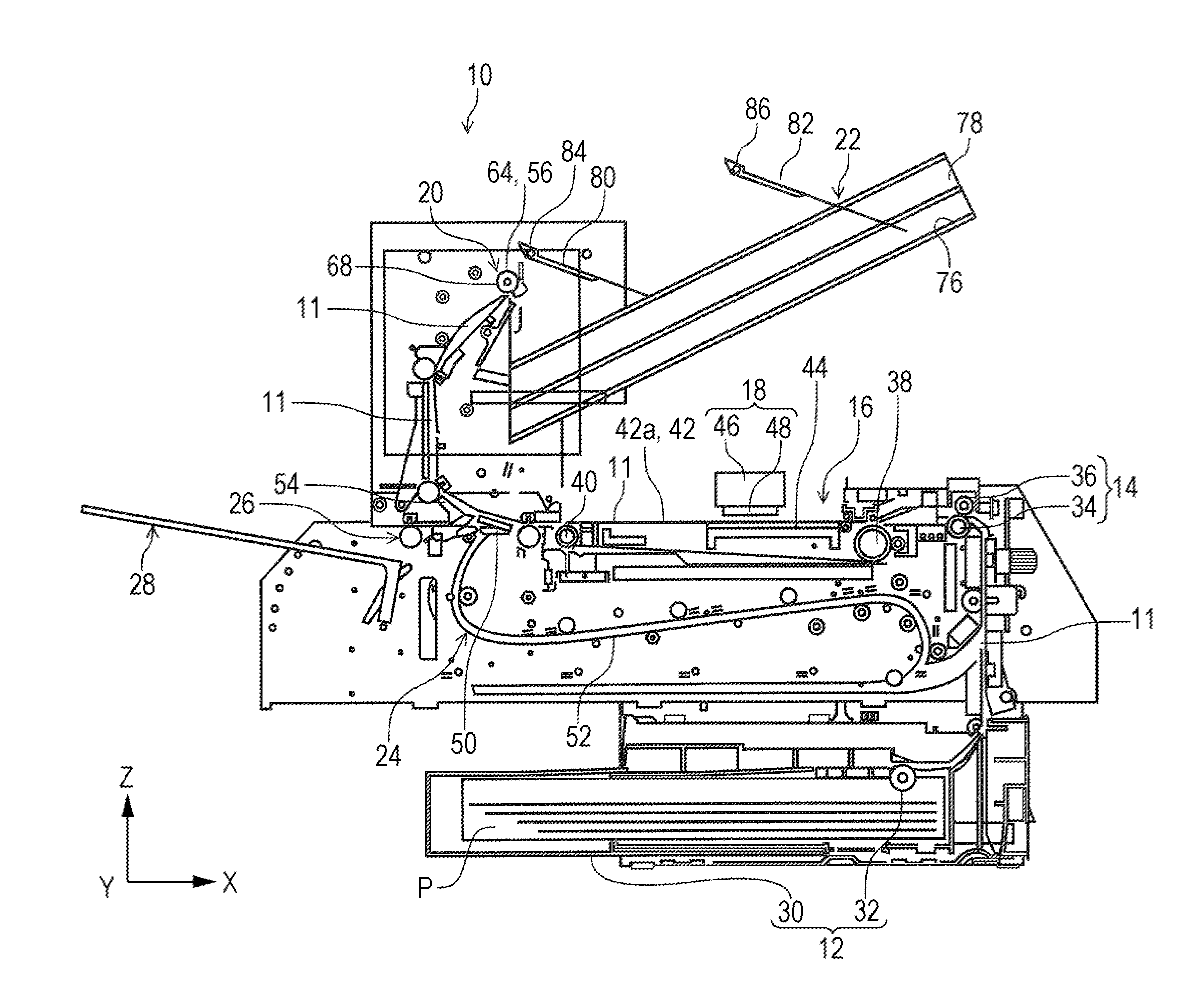
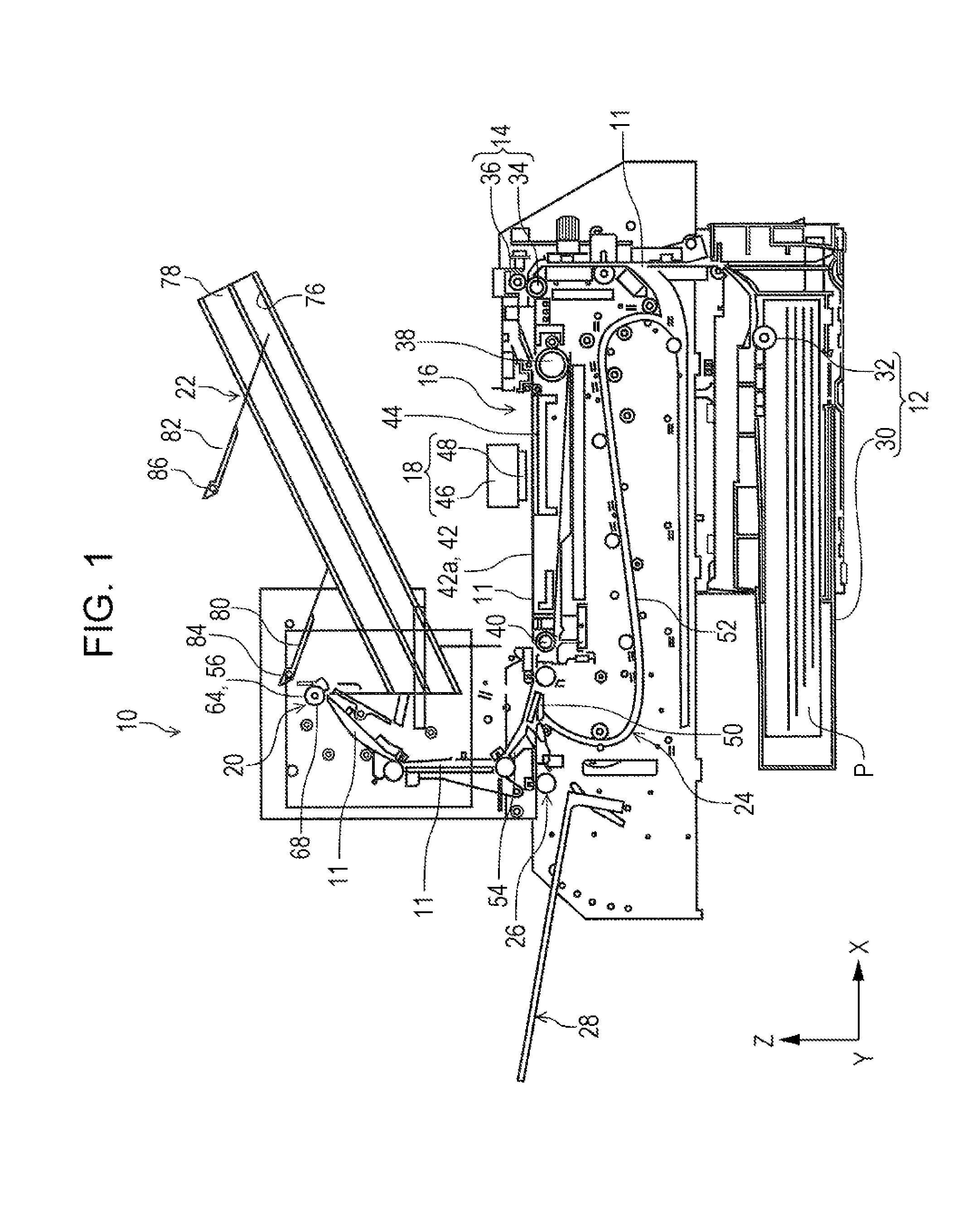
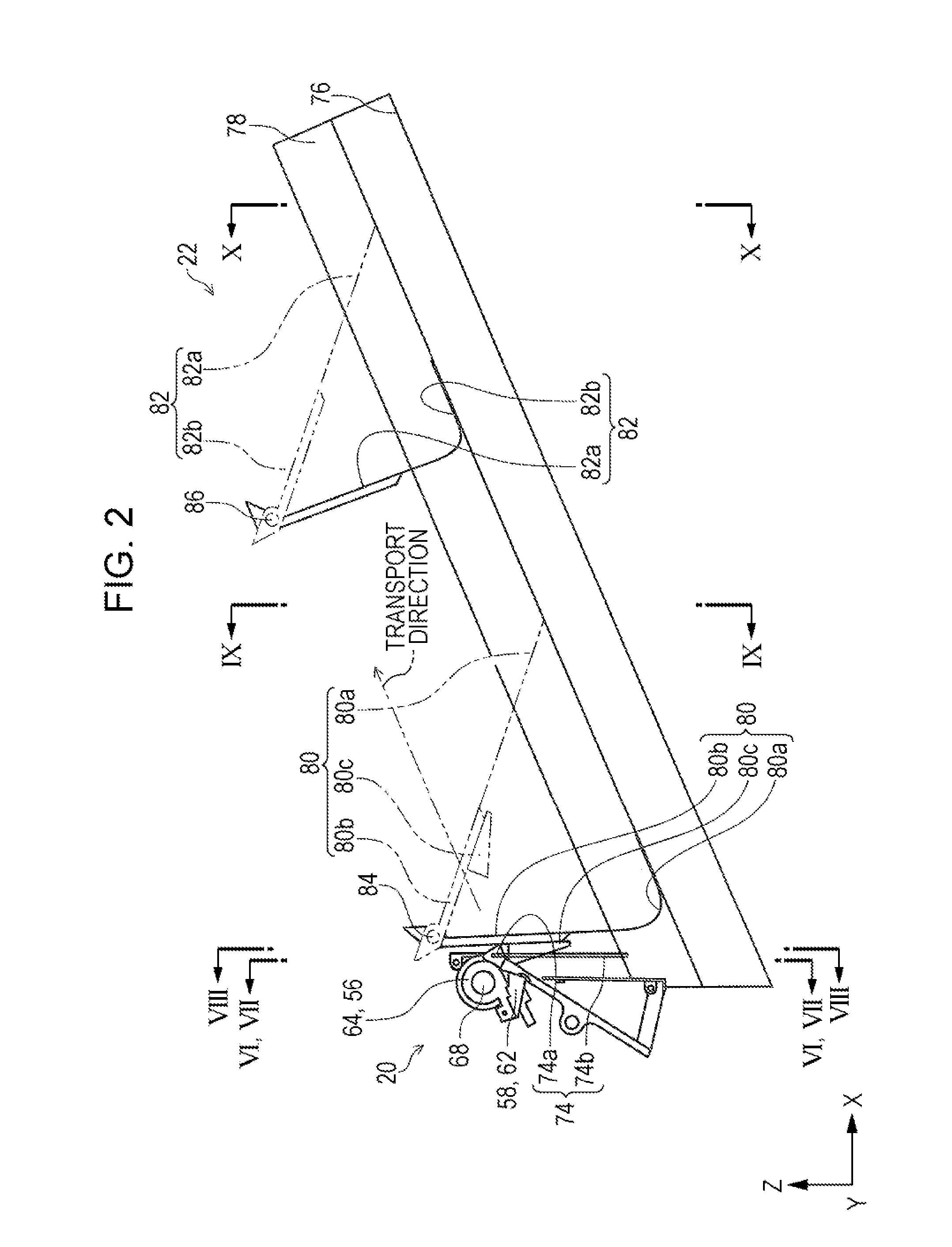
[0074]Next, structures of the Fd discharge section 20 as the “discharge section,” the Fd mounting section 22 as the “mounting section,” and the like of the recording apparatus according to the first embodiment will be described in order with reference to FIGS. 2 to 5.

Discharge Section

[0075]The Fd discharge section 20 has a plurality of discharge rollers 56, and first bending members 58 are disposed on a further upstream side of the transport direction than nip positions 70 (described later) of the discharge rollers 56 in the transport path 11. In this embodiment, the first bending member 58 has a first deformation member 60 and a second deformation member 62. The first bending member 58 can also be configured to have only the first deformation member 60.

[0076]The plurality of discharge rollers 56 have discharge driving rollers 64 and discharge driven rollers 66 that form pairs.

[0077]A plurality of the discharge driving rollers 64 are disposed in a driving shaft 68 at predetermined i...

modification example of first embodiment

[0166](1) In this embodiment, the first deformation member 60 and the second deformation member 62 are configured to be capable of swinging with respect to the frame 72. However, at least one of the first deformation member 60 and the second deformation member 62 may be configured to be fixed to the frame 72 or both thereof may be configured to be fixed thereto.

[0167](2) In this embodiment, the first deformation member 60 and the second deformation member 62 are configured to be biased to the transport path due to the weight thereof. However, another biasing means such as a spring, hydraulic pressure, and pneumatic pressure may be used, instead of the weight thereof or in addition to the weight thereof, as means for biasing at least one of the first deformation member 60 and the second deformation member 62.

[0168](3) In this embodiment, at least one of the first biasing member 80 and the second biasing member 82 is configured to rotate with respect to the support shafts 84 and 86. I...


PUM

PropertyMeasurementUnit
Lengthaaaaaaaaaa
Widthaaaaaaaaaa
Distanceaaaaaaaaaa

Abstract

A recording apparatus includes a recording unit that performs recording on a recording surface of a recording medium, a discharge section that discharges the recording medium, and a first bending member that is in contact with the recording medium which passes through the recording unit in the transport path and is transported toward the discharge section to bend the recording medium, in which the first bending member bends the recording medium in such a manner that the recording surface is directed inside by displacing both side portions of the recording medium in a width direction with respect to a central portion of the recording medium in the width direction of the recording medium at a position on a further upstream side in a direction of the transport than a contact position of the discharge section where a feeding force is applied to the recording medium.

Description

BACKGROUND[0001]1. Technical Field[0002]The present invention relates to a recording apparatus in which recording is performed on a recording medium by using a liquid such as ink and, more particularly, to parts that transport and discharge the recording medium on which recording is performed.[0003]In the present application, ink jet type serial printers, line printers, copiers, fax machines and the like are included in the recording apparatus.INCORPORATED BY REFERENCE[0004]The entire disclosure of Japanese Patent Application No. 2013-072445, filed Mar. 29, 2013 is expressly incorporated by reference herein.[0005]2. Related Art[0006]In the related art, ink jet type recording apparatuses are in wide use as this type of recording apparatus. JP-A-2002-326755, JP-A-2005-280214, and JP-A-2011-235494 are examples of the related art. In JP-A-2002-326755, a face-up type structure is used in a part of the ink jet type recording apparatus (hereinafter referred to as “printer”) that discharges...

Claims


Application Information

Patent Timeline
IPC IPC(8): B41J11/00
CPCB41J11/0005B41J13/106B65H29/70B65H2404/1115B65H2301/51214B65H2301/5121
Inventor KODAMA, HIDETOSHICHIBA, SATOSHI
Owner SEIKO EPSON CORP
Why Eureka
Try Eureka