Voltage balancing system and method for multilevel converters

a voltage balancing and multi-level converter technology, applied in the field of multi-level converters, can solve the problems of voltage and under voltage trips during the operation of the converter, increase in output voltage total harmonic distortion (thd), and control loop instability

Active Publication Date: 2014-10-02
GENERAL ELECTRIC CO
View PDF4 Cites 49 Cited by
  • Summary
  • Abstract
  • Description
  • Claims
  • Application Information

AI Technical Summary

Benefits of technology

[0006]In accordance with an embodiment of the present invention, a method of operating a flying capacitor multilevel converter including a direct current link and a plurality of phase legs each having a plurality of flying capacitors is provided. The method includes employing redundant states to balance flying capacitor voltages by charging or discharging flying capacitors. Employing redundant states includes obtaining a load current of the flying capacitor multilevel converter and utilizing a capacitor current of a phase terminal capacitor to determine redundant states when a load current value is lower than a threshold value. When the load current value is higher than the threshold value a load current direction is utilized to determine redundant states.

Problems solved by technology

Voltage balancing of flying capacitors is a challenge when operating the flying capacitor multilevel converter.
Flying capacitors voltage unbalance (i.e., unequal voltages across flying capacitors) may overstress the capacitors and switching devices and cause over voltage and under voltage trips during the operation of the converter.
Flying capacitors voltage unbalance also causes an increase in output voltage total harmonic distortion (THD) and may cause the control loop to become unstable.
However, the balancing circuitry adds cost, losses, volume to the flying capacitor multilevel converter and also needs to be designed carefully.

Method used


Image

  • Voltage balancing system and method for multilevel converters
  • Voltage balancing system and method for multilevel converters
  • Voltage balancing system and method for multilevel converters

Examples


Embodiment Construction

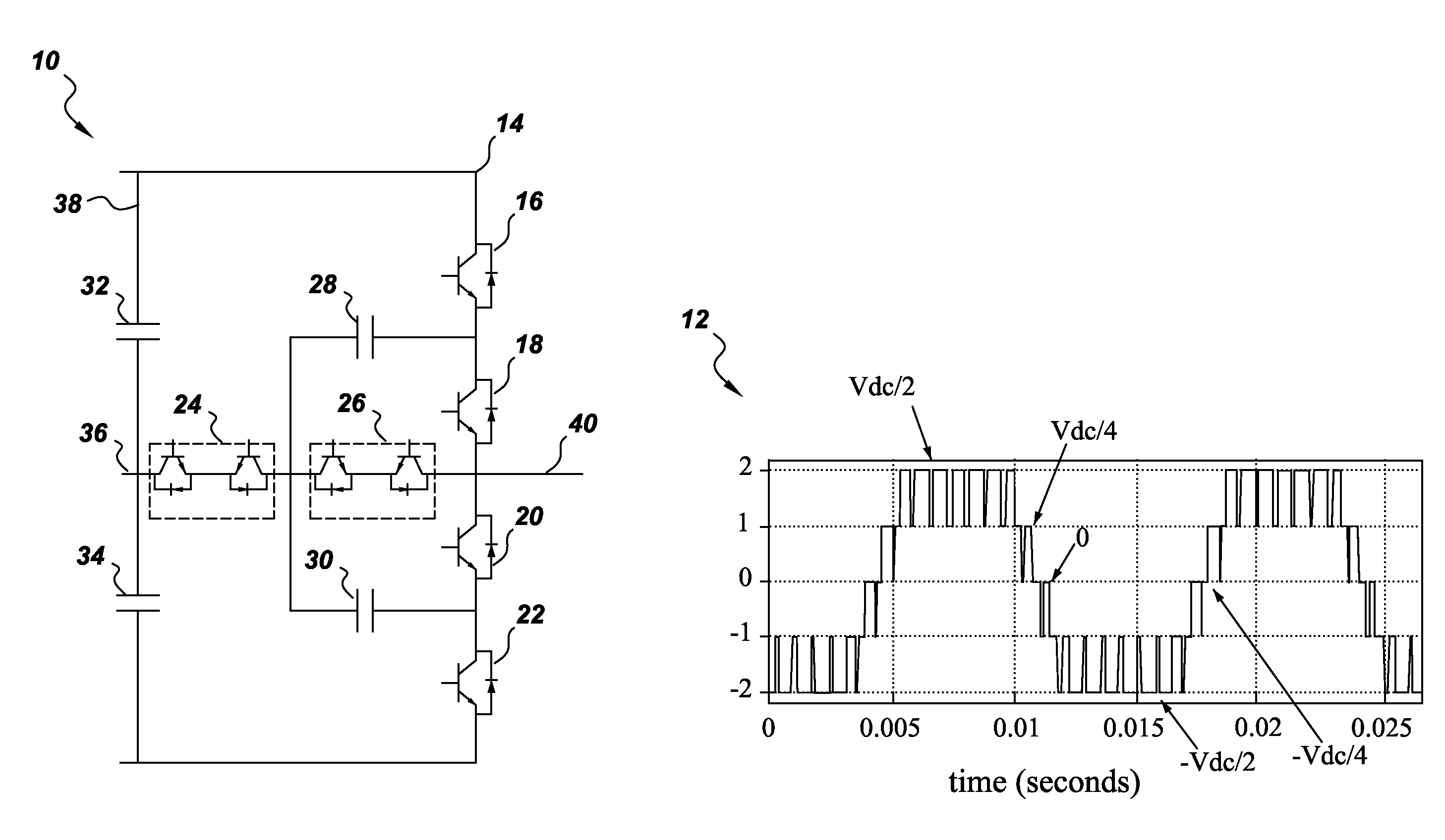
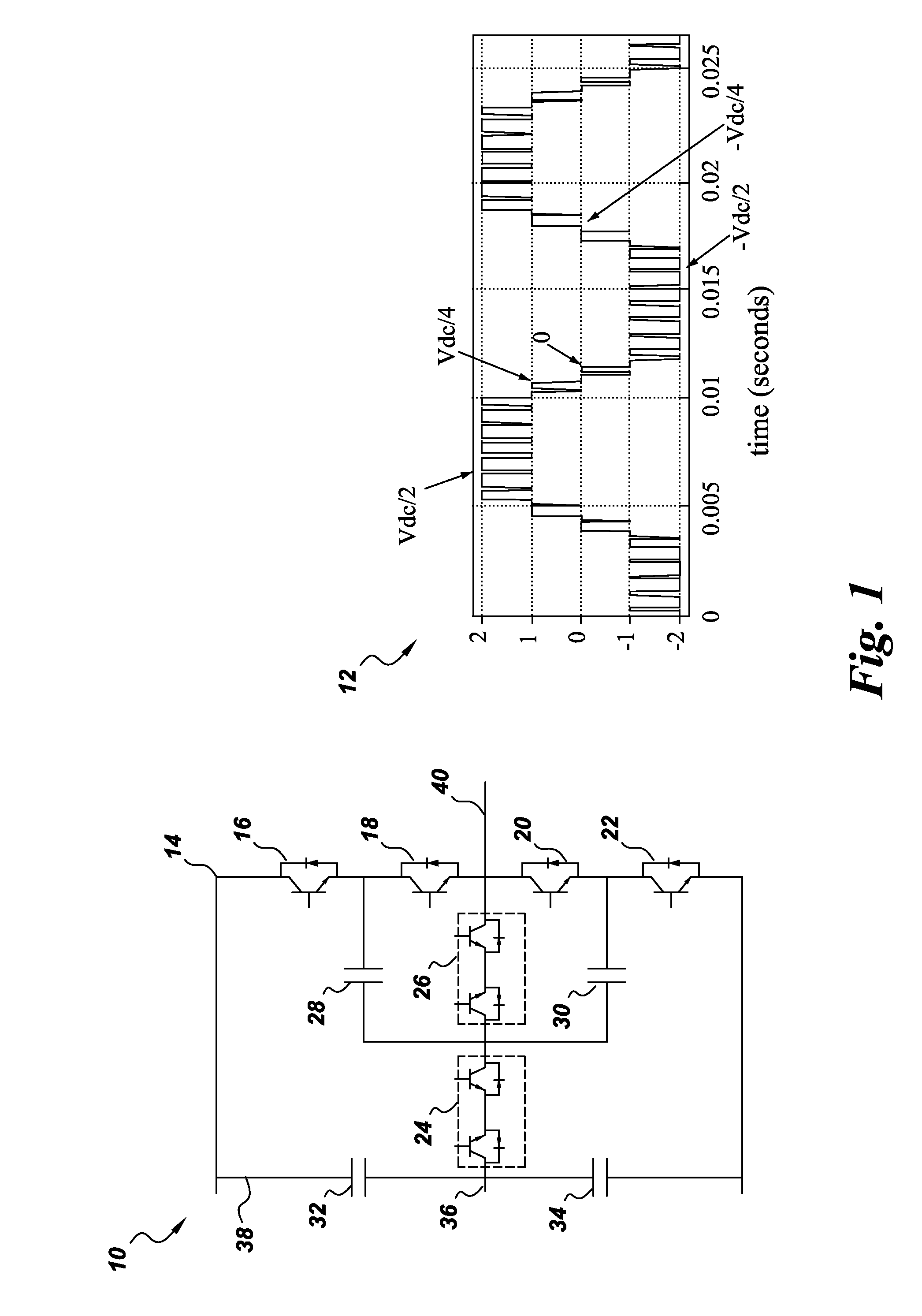
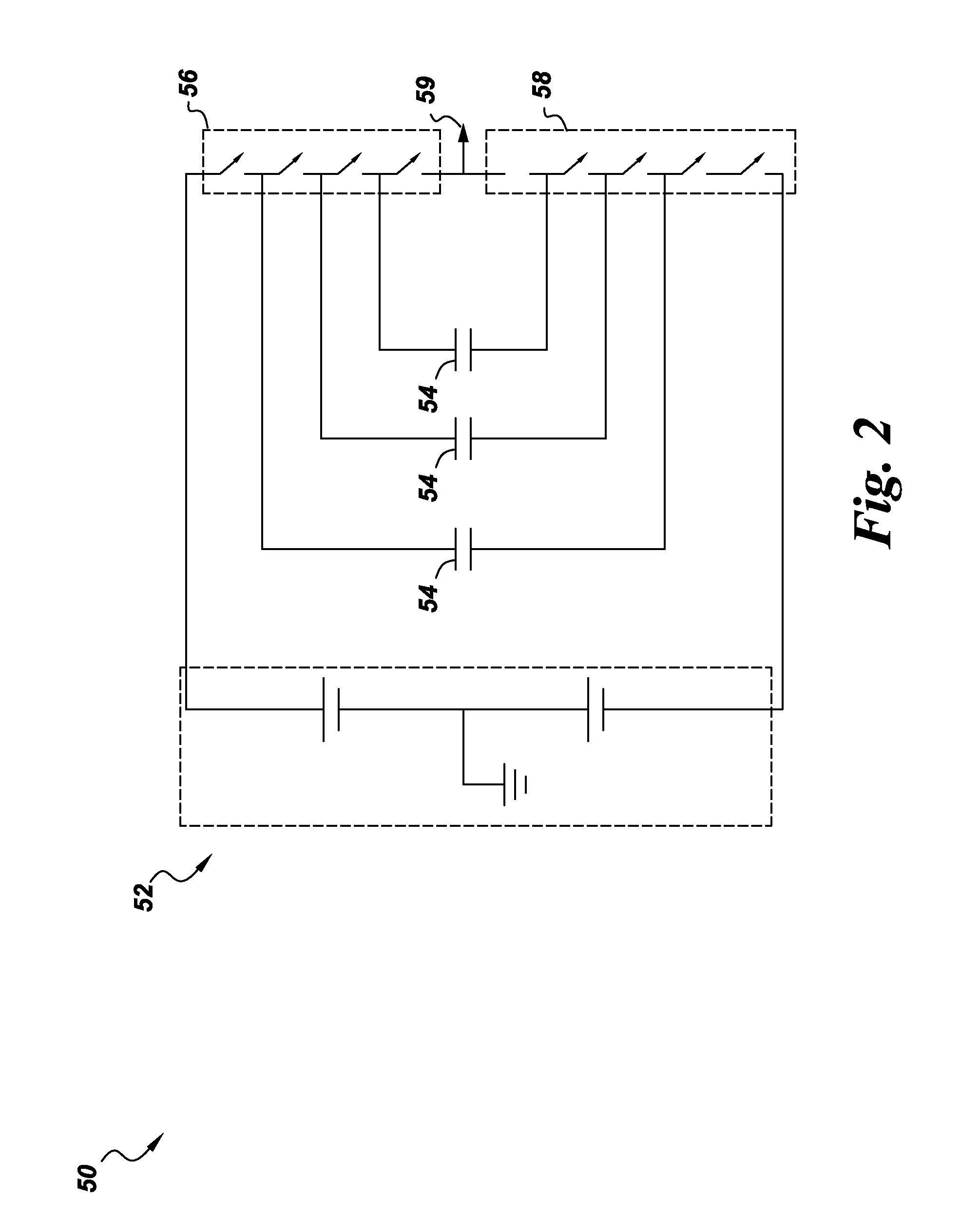
[0015]FIG. 1 illustrates a schematic 10 of one leg or one phase of an exemplary flying capacitor (FC) multilevel converter and its output waveform 12. It should be noted that schematic 10 is only an example of the flying capacitor multilevel converter and other variations of flying capacitor multilevel converter such as one shown in FIG. 2 are well within the scope of the present technique. One leg 14 of the flying capacitor multilevel converter includes four unidirectional switching devices 16, 18, 20, and 22, two bidirectional switching devices 24 and 26 and two flying capacitors 28 and 30. In one embodiment, two direct current (DC) link capacitors 32 and 34 are controlled each to have a voltage about equal to Vdc / 2, where Vdc is the total DC link voltage. An output phase voltage Van of leg 14 is measured between a center point or a neutral point 36 of a DC link 38 and a phase terminal 40. As shown in output waveform 12, output phase voltage Van has five voltage levels, two positi...


PUM


Abstract

A method of operating a flying capacitor multilevel converter having a direct current link and a plurality of phase legs each having a plurality of flying capacitors includes employing redundant states to balance flying capacitor voltages by charging or discharging flying capacitors. The redundant states are employed by obtaining a load current of the flying capacitor multilevel converter. If a load current value is lower than a threshold value then a capacitor current of a phase terminal capacitor is utilized to determine redundant states else a load current direction is utilized to determine the redundant states.

Description

BACKGROUND[0001]Embodiments of invention relates to multilevel converters and more specifically to a system and method for voltage balancing in multilevel converters.[0002]Multilevel converters are generally used in high power industrial applications such as variable speed drive (VSD) systems or in energy conversion applications such as a solar (or photovoltaic) power generation systems, wind turbine generators and high voltage direct current (HVDC) transmission systems. One example of a multi-level converter is a flying capacitor (FC) multilevel converter. The flying capacitor multilevel converter includes a number of capacitors referred to as flying capacitors. The flying capacitors are charged to various voltage levels and by changing switching states the flying capacitors and a dc source are connected in different ways and produce various line-to-neutral output voltages.[0003]Voltage balancing of flying capacitors is a challenge when operating the flying capacitor multilevel con...

Claims


Application Information

Patent Timeline
Patent Type & Authority Applications(United States)
IPC IPC(8): H02M7/483H02M1/00H02M7/487
CPCH02M7/483H02M7/487H02M1/0012H02M1/0009H02M1/0095H02M7/4837H02M7/4833
Inventor SCHROEDER, STEFANCHEN, QUINGYUN
Owner GENERAL ELECTRIC CO
Why Eureka
Try Eureka