
Inductive displacement sensor

Inactive Publication Date: 2014-10-09
CONTINENTAL TEVES AG & CO OHG
View PDF1 Cites 14 Cited by
  • Summary
  • Abstract
  • Description
  • Claims
  • Application Information

AI Technical Summary

Benefits of technology

This invention is based on the idea that an eddy current sensor can be made using affordable materials in a compact way, without requiring a magnet or magnet carrier. The sensor uses a different physical principle, depending on the energy source it receives, which reduces aging and failure. Additionally, the invention utilizes a tandem master cylinder, which allows for two brake circuits that meet legal standards for passenger vehicles.

Problems solved by technology

However, this magnet requires a great deal of space.
In addition, the measuring principle depends upon the magnetic field inside the magnet and this magnetic field is not permanently constant since it weakens over a period of time.
Although an electromagnet could overcome this disadvantage, said electromagnet could however render the construction technically complicated.
In addition, the individual components for achieving the measuring principle are expensive.
However, this distance measurement necessitates that the conventional eddy current sensor also requires a very large amount of space since the generation of a magnetic field alone by means of the coil itself requires a large amount of space.

Method used


Image

  • Inductive displacement sensor
  • Inductive displacement sensor
  • Inductive displacement sensor

Examples


Embodiment Construction

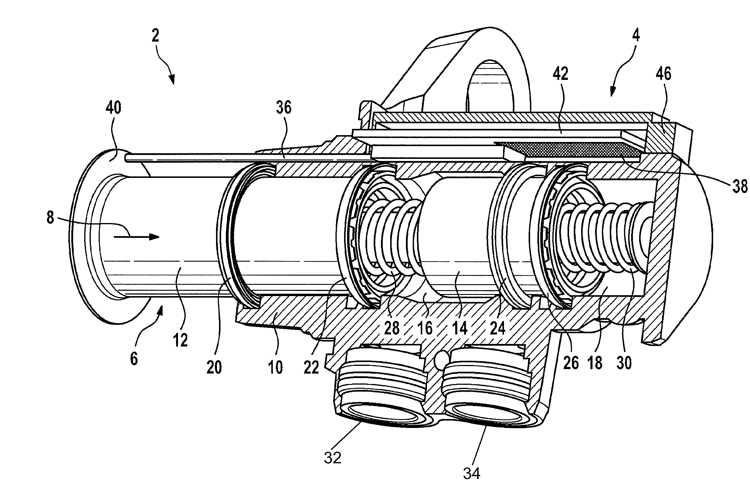
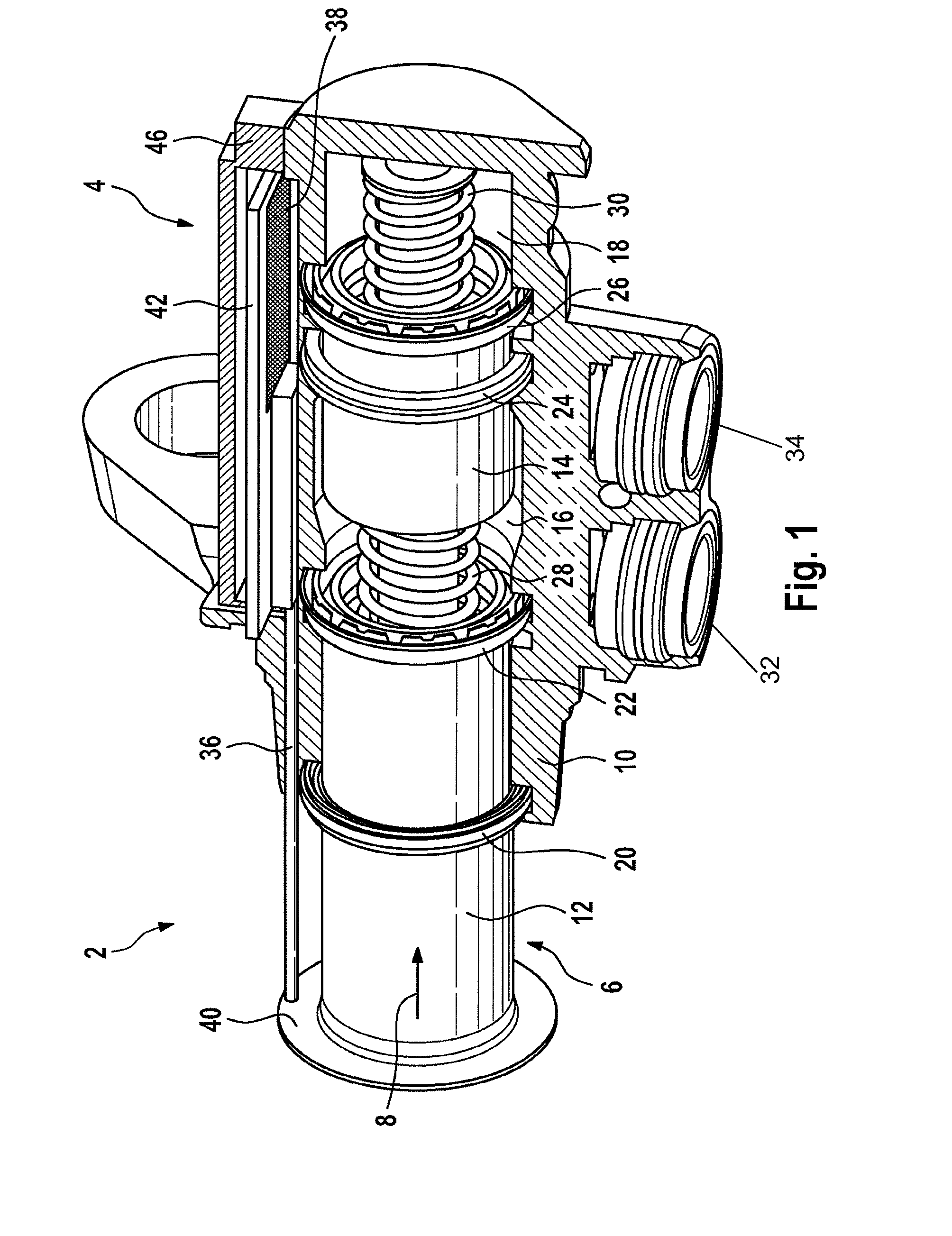
[0026]Reference is made to FIG. 1 that illustrates a tandem master cylinder 2 together with the inductive displacement sensor 4 in accordance with the invention. Furthermore, the tandem master cylinder 2 comprises a pressure piston 6 that is arranged in such a manner as to be able to move in a direction of movement 8 in a housing 10, wherein the movement of the pressure piston 6 can be controlled by means of a foot pedal (not illustrated). The pressure piston 6 itself is divided into a primary piston 12 and a secondary piston 14, wherein the primary piston 12 closes an inlet of the housing 10 and the secondary piston 14 divides the inner chamber of the housing 10 into a primary chamber 16 and a secondary chamber 18. A secondary collar 20 is arranged on the primary piston 12 in the region of the inlet of the housing 10 and said secondary collar insulates the inner chamber of the housing 10 from the environmental air. A primary collar 22 is arranged downstream of the secondary collar ...


PUM


Abstract

Inductive displacement sensor includes a coil and a target which is movable relative to the coil in a direction of movement, wherein an inductance of the coil is dependent on a position of the target relative to the coil, wherein the coil and the target at least partially overlap in the direction of movement.

Description

CROSS REFERENCE TO RELATED APPLICATION[0001]This application is the U.S. National Phase Application of PCT International Application No. PCT / EP2012 / 071745, filed Nov. 2, 2012, which claims priority to German Patent Application No. 10 2011 085 740.0 filed Nov. 3, 2011, the contents of such applications being incorporated by reference herein.FIELD OF THE INVENTION[0002]The present invention relates to an inductive displacement sensor as claimed in claim 1, a master cylinder as claimed in claim 5, a vehicle as claimed in claim 9 and a method as claimed in claim 10.BACKGROUND OF THE INVENTION[0003]As is known from DE 40 04 065 A1, which is incorporated by reference, displacement sensors are used for measuring the position of a pressure piston in a master cylinder.[0004]By way of example, eddy current sensors could be used for this purpose, as they are known by way of example from DE 196 31 438 A1, which is incorporated by reference.SUMMARY OF THE INVENTION[0005]An aspect of the inventio...

Claims


Application Information

Patent Timeline
IPC IPC(8): G01B7/00B60T7/04B60T8/17B60T17/22
CPCB60T17/221G01D5/2006B60T7/042G01B7/003B60T8/17B60T17/22B60T11/16
Inventor MULLER, HILMARLEHMANN, SORENHAVERKAMP, MARTIN
Owner CONTINENTAL TEVES AG & CO OHG
Learn More