
Adjustment device and method for adjusting chrominance and luminance of display device

a technology of chrominance and luminance adjustment and display device, which is applied in the field of display adjustment technology, can solve the problems of low accuracy of adjustment, inconvenient user adjustment of chrominance and luminance of each screen, and expensive adjustment device us

Inactive Publication Date: 2014-10-09
FIH (HONG KONG) LTD
View PDF5 Cites 10 Cited by
  • Summary
  • Abstract
  • Description
  • Claims
  • Application Information

AI Technical Summary

Benefits of technology

The present patent relates to an adjustment device and method for adjusting the chrominance and luminance of a display device. The technical effect of the patent is to provide an improved method for adjusting the display device that allows for higher accuracy and efficiency, while also reducing the complexity and cost of the adjustment system. The adjustment device includes a camera and wireless modules for capturing images and communicating with the display device, and a computing module for analyzing and adjusting the images. The method involves capturing an image of a predetermined image displayed on the display device, acquiring the image, and analyzing the image to determine the appropriate adjustments. The adjustments can be made to the chrominance, luminance, or both. The method can be used with both single and multiple screens, and can be used with different types of display devices such as televisions, computers, and smart phones.

Problems solved by technology

Generally, chrominance and luminance of display devices needs manually adjusted by observing the display devices, therefore accuracy of the adjustment is low.
If high accuracy is required for the chrominance and luminance of the display devices, expensive adjustment devices need to be used.
In addition, when a display device includes a plurality of split screens, it is inconvenient for the users to adjust the chrominance and luminance of each screen.

Method used


Image

  • Adjustment device and method for adjusting chrominance and luminance of display device
  • Adjustment device and method for adjusting chrominance and luminance of display device
  • Adjustment device and method for adjusting chrominance and luminance of display device

Examples


Embodiment Construction

[0009]The present disclosure, including the accompanying drawings, is illustrated by way of examples and not by way of limitation. It should be noted that references to “an” or “one” embodiment in this disclosure are not necessarily to the same embodiment, and such references mean “at least one.”

[0010]In general, the word “module,” as used hereinafter, refers to logic embodied in hardware or firmware, or to a collection of software instructions, written in a programming language, such as, for example, Java, C, or assembly. One or more software instructions in the modules may be embedded in firmware. It will be appreciated that modules may comprise connected logic units, such as gates and flip-flops, and may comprise programmable units, such as programmable gate arrays or processors. The modules described herein may be implemented as either software and / or hardware modules and may be stored in any type of non-transitory computer-readable storage medium or other computer storage devic...


PUM


Abstract

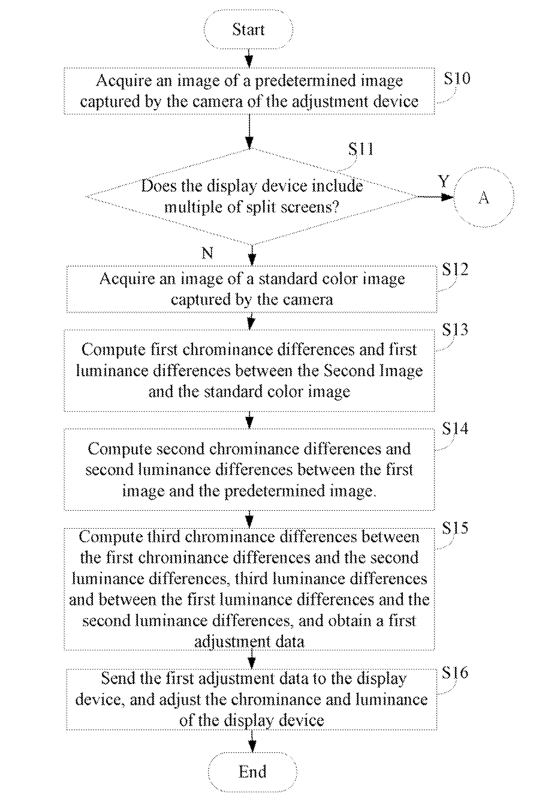
An adjustment device including a camera is connected to a display device. An image of a predetermined image displayed on the display device, and an image of a standard color image are captured by the camera. First chrominance differences and first luminance differences between the image corresponding to the standard color image and the standard color image are computed. Second chrominance differences and second luminance differences between the image corresponding to the predetermined image and the predetermined image are computed. Third chrominance differences between the first chrominance differences and the second chrominance differences, and third luminance differences between the first luminance differences and the second luminance differences are computed. According to third chrominance differences and third luminance differences, first adjustment data is obtained. The first adjustment data is sent to the display device. According to the first adjustment data, c. Chrominance and luminance of the display device is adjusted.

Description

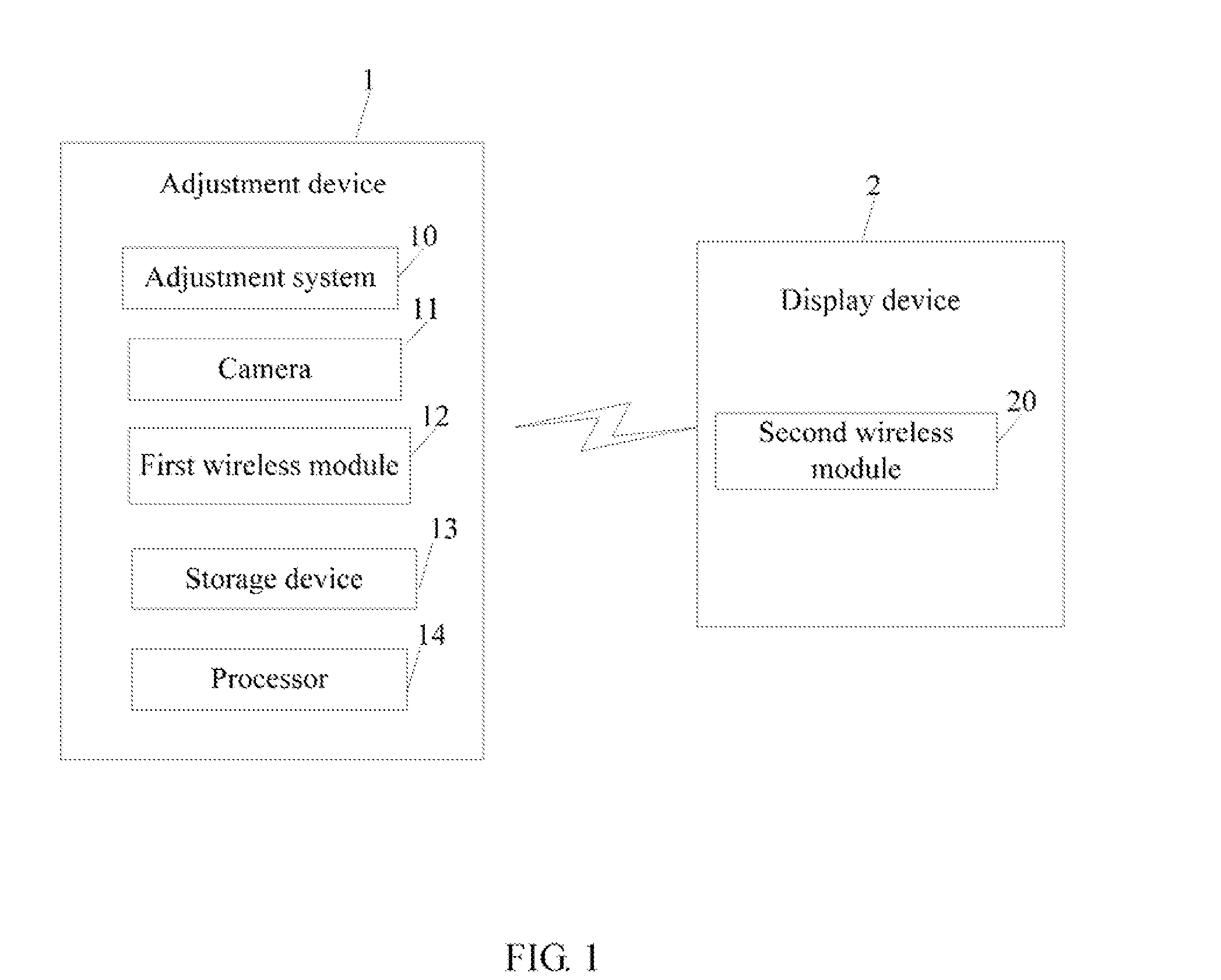
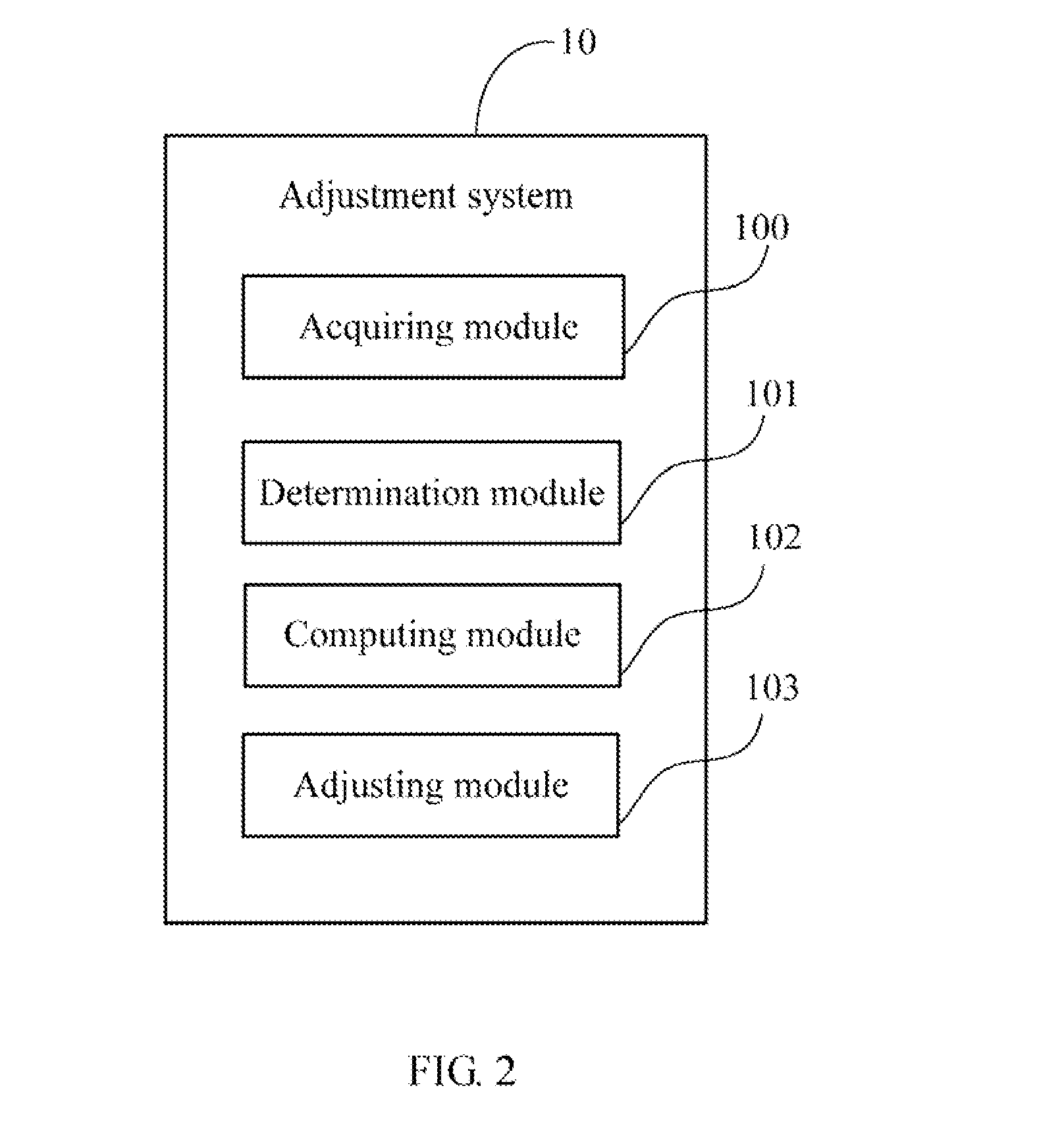
BACKGROUND[0001]1. Technical Field[0002]Embodiments of the present disclosure relate to display adjustment technology, and particularly to an adjustment device and a method for adjusting chrominance and luminance of a display device.[0003]2. Description of Related Art[0004]Generally, chrominance and luminance of display devices needs manually adjusted by observing the display devices, therefore accuracy of the adjustment is low. If high accuracy is required for the chrominance and luminance of the display devices, expensive adjustment devices need to be used. In addition, when a display device includes a plurality of split screens, it is inconvenient for the users to adjust the chrominance and luminance of each screen.BRIEF DESCRIPTION OF THE DRAWINGS[0005]FIG. 1 is a block diagram of one embodiment of an adjustment device including an adjustment system.[0006]FIG. 2 is a block diagram of one embodiment of function modules of the adjustment system in the adjust device of FIG. 1.[0007...

Claims


Application Information

Patent Timeline
Patent Type & Authority Applications(United States)
IPC IPC(8): G09G5/02G06F3/14G06T7/40
CPCG09G5/02G06T7/408G06F3/1446G06T2207/10024G06T2207/30121G09G2320/0626G09G2320/0666G09G2320/0693G09G2320/08G06T7/90
Inventor CHENG, LI-CHIEHHSU, YI-SHENGCHANG, WEN-HSIN
Owner FIH (HONG KONG) LTD
Learn More