
Ring laser gyro

a laser gyro and ring technology, applied in the field of ring laser gyro, can solve problems such as and achieve the effect of not degrading the accuracy of angular velocity signals

Active Publication Date: 2014-10-09
JAPAN AVIATION ELECTRONICS IND LTD
View PDF0 Cites 1 Cited by
  • Summary
  • Abstract
  • Description
  • Claims
  • Application Information

AI Technical Summary

Benefits of technology

The invention describes a device that detects the position of a laser beam and controls the movement of a dither mechanism based on that position. The device uses a piezoelectric element to detect the position of the laser beam, but this method can be affected by temperature variations. The new invention uses the positional information from the laser beam detector to control the dither mechanism, so the accuracy of the signal is not affected by these disturbances. The technical effect is that the device can detect and control the movement of the dither mechanism with high accuracy.

Problems solved by technology

In the ring laser gyros having the structure as described above, disturbances such as temperature variations of the dither mechanism distort the piezoelectric elements for dither detection and affect the detected voltages, thereby degrading the accuracy of the angular velocity signals.

Method used


Image

  • Ring laser gyro
  • Ring laser gyro
  • Ring laser gyro

Examples


Embodiment Construction

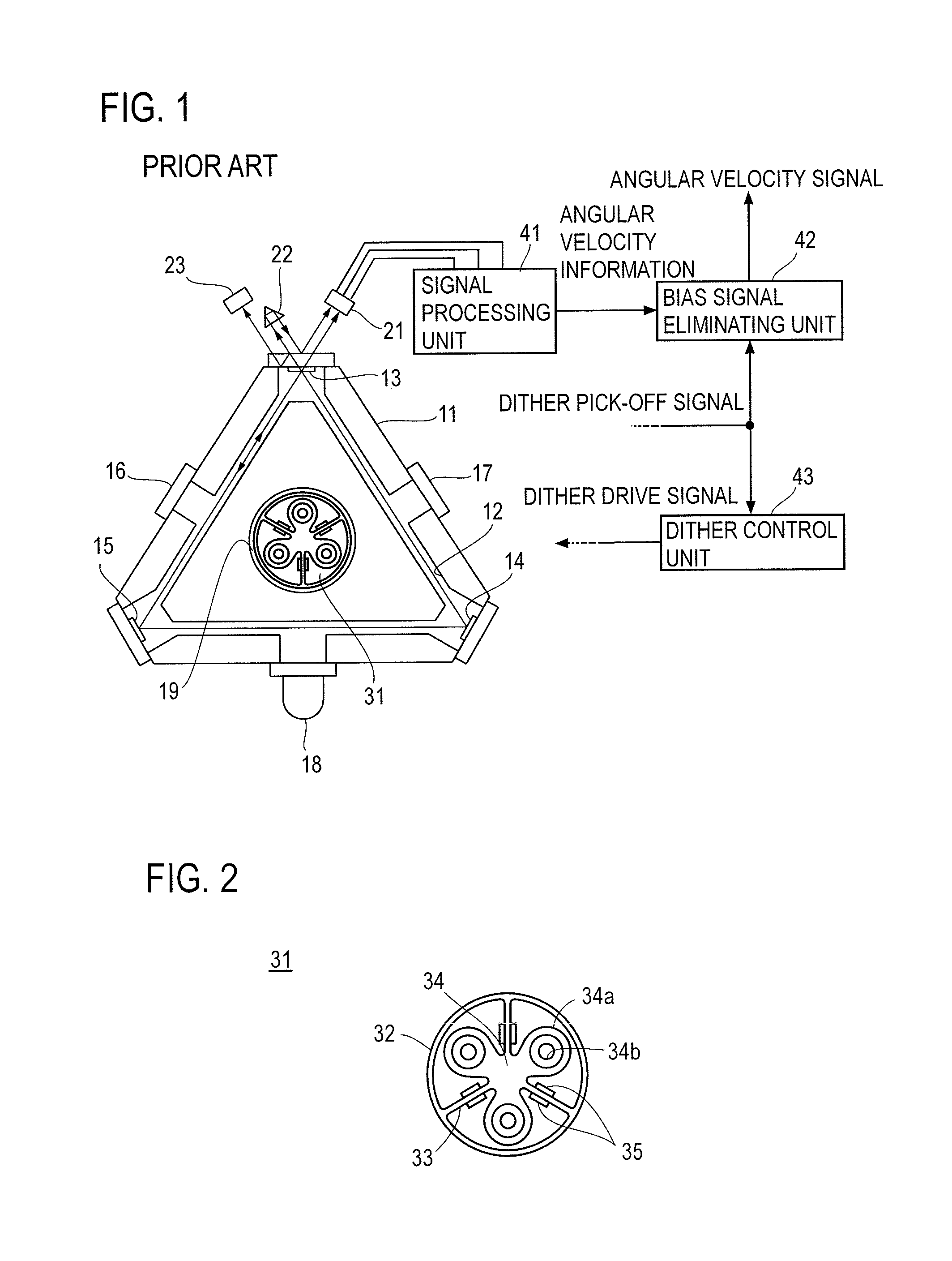
[0025]Referring now to the drawings, an embodiment of the present invention will be described. Here, differences between the embodiment of the present invention and the prior art will be described without duplicating the description of components common to the prior art which are denoted by the same reference numerals.

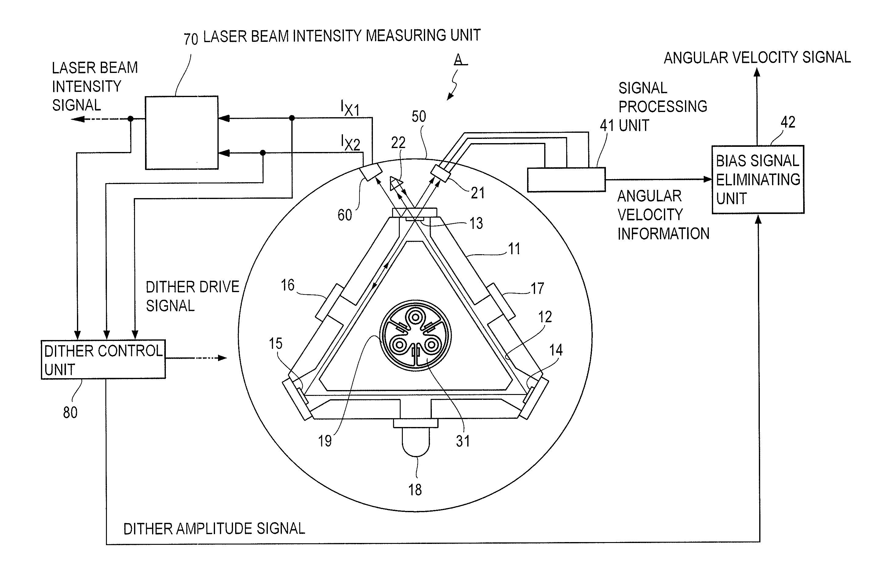
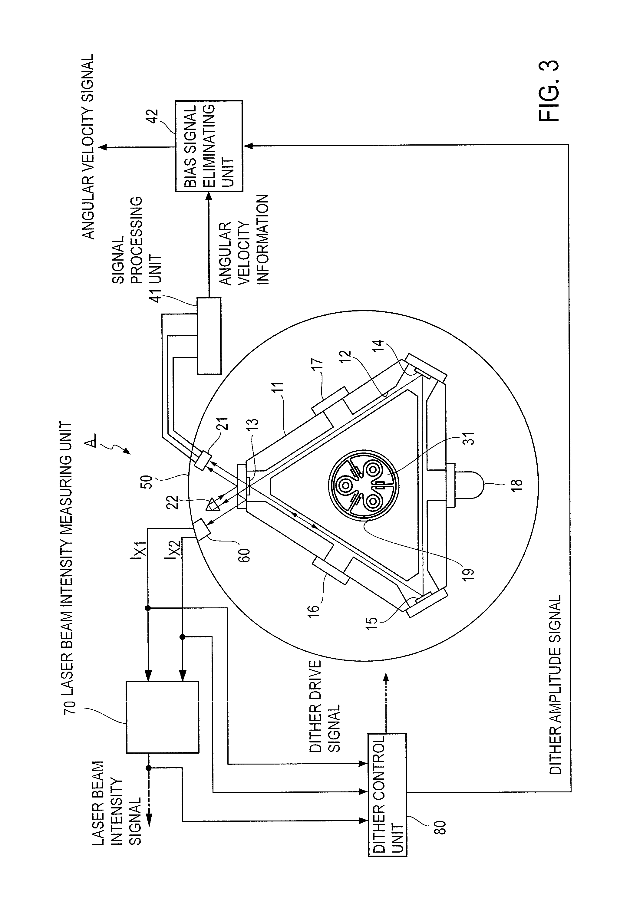
[0026]A ring laser gyro A in the embodiment shown in FIG. 3 includes, instead of the laser beam intensity detector 23 provided in conventional ring laser gyros, a laser beam receiving unit 60 for receiving one of the laser beams taken out of a gyro block 11 for oscillating laser beams and a laser beam intensity measuring unit 70 for measuring the intensity of the laser beam received by the laser beam receiving unit 60. The laser beam receiving unit 60 is secured to a gyro case 50 housing the gyro block 11. The ring laser gyro A also includes a dither control unit 80, instead of the dither control unit 43 provided in the conventional ring laser gyros.

[0027]The laser bea...


PUM


Abstract

A ring laser gyro with no piezoelectric elements for dither detection includes a laser beam receiving unit for receiving a laser beam taken out of a gyro block, a laser beam intensity measuring unit for measuring the intensity of the laser beam received by the laser beam receiving unit, a dither mechanism, a dither control unit for driving the dither mechanism, and a gyro case housing the gyro block, wherein the laser beam receiving unit is secured to the gyro case, the laser beam receiving unit has a laser beam receiving surface for receiving the laser beam from the gyro block to detect a laser beam receiving position on the laser beam receiving surface and output positional information indicating the laser beam receiving position. The dither control unit drives the dither mechanism on the basis of information indicating the amplitude of the laser beam receiving position obtained from the positional information.

Description

TECHNICAL FIELD [0001]The present invention relates to a ring laser gyro not employing piezoelectric elements for dither detection.BACKGROUND ART [0002]Referring to FIG. 1, a conventional ring laser gyro will be outlined. A gyro block 11 made of glass has a triangular path 12 formed therewithin and mirrors 13, 14, 15 disposed on the apexes of the triangle formed by the path 12. The path 12 has a laser medium enclosed therewithin and anodes 16, 17 and cathode 18 disposed on the sides of the path 12. When a high voltage is applied across the anodes 16, 17 and cathode 18, the laser medium is excited and clockwise and counterclockwise laser beams oscillate. The clockwise and counterclockwise laser beams reflect off the mirrors 13, 14, 15 and propagate through the path 12 in a triangular ring shape. The optical paths of the laser beams will be referred to hereinafter as ring-shaped optical paths.[0003]If an angular velocity is input into the gyro block 11 in this state, a difference aris...

Claims


Application Information

Patent Timeline
IPC IPC(8): G01C19/68
CPCG01C19/68G01C19/70
Inventor IIZUKA, KEIYOSHIOKA, KAZUNORIYAMAMOTO, NAOKI
Owner JAPAN AVIATION ELECTRONICS IND LTD
Features
  • Generate Ideas
  • Intellectual Property
  • Life Sciences
  • Materials
  • Tech Scout
  • Unparalleled Data Quality
  • Higher Quality Content
  • 60% Fewer Hallucinations
Learn More