
MEMS scanning micromirror

a micro-mirror and scanning technology, applied in the field of micro-electromechanical systems, can solve the problems of reducing the image quality of the scanner display, unable to achieve high image resolution, and affecting the operation of the scanner body, so as to avoid the increase of the rotational inertia of the mirror body and avoid the high tensile stress of the cantilever beam

Active Publication Date: 2014-10-09
INNOLUCE
View PDF12 Cites 48 Cited by
  • Summary
  • Abstract
  • Description
  • Claims
  • Application Information

AI Technical Summary

Benefits of technology

The invention is a MEMS scanning micromirror with a frame and mirror body, and a cantilever beam assembly. The assembly includes a cantilever beam with a relief means that allows it to translate longitudinally and is connected between the frame and mirror body. The cantilever beam has a smaller thickness than its width and is designed to set the torsional stiffness about the rotation axis, while the effect of the vertical support beams is negligible. This design helps to avoid high tensile stresses and increases in rotational inertia of the mirror body.

Problems solved by technology

Problems with image quality in MEMS scanning micromirrors occur due to two effects: undesired rigid body motion of the mirror, and mirror deformation (either static or dynamic).
If the image quality is too poor due to such effects then a high image resolution cannot be achieved, which is especially undesirable for larger displays.
Out-of-plane rocking and vertical translation resonant modes greatly reduce the image quality of the scanner display.
The micromirror's static and dynamic deformation also reduce the image quality of the scanner display.
Unfortunately, the image resolution is proportional to the product of scanning angle and micromirror diameter.

Method used


Image

  • MEMS scanning micromirror
  • MEMS scanning micromirror
  • MEMS scanning micromirror

Examples


Embodiment Construction

[0036]In the following detailed description numerous specific details are set forth in order to provide a thorough understanding of the present invention. However, it will be understood by one skilled in the art that the present invention may be practiced without these specific details. In other instances, well known methods, procedures, and components have not been described in detail so as not to obscure aspects of the present invention.

[0037]The invention is described more fully hereinafter with reference to the accompanying drawings, in which embodiments of the invention are shown. This invention may, however, be embodied in many different forms and should not be construed as limited to the embodiments set forth herein. Rather, these embodiments are provided so that this disclosure will be thorough and complete, and will fully convey the scope of the invention to those skilled in the art. In the drawings, the size and relative sizes of layers and regions may be exaggerated for c...


PUM


Abstract

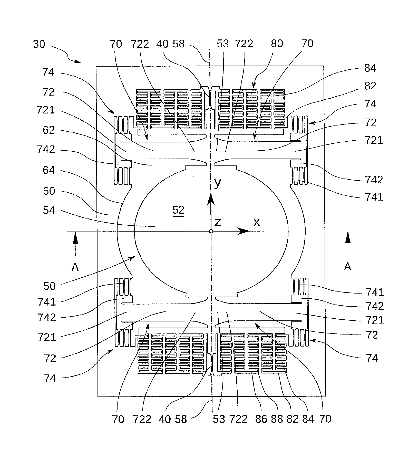
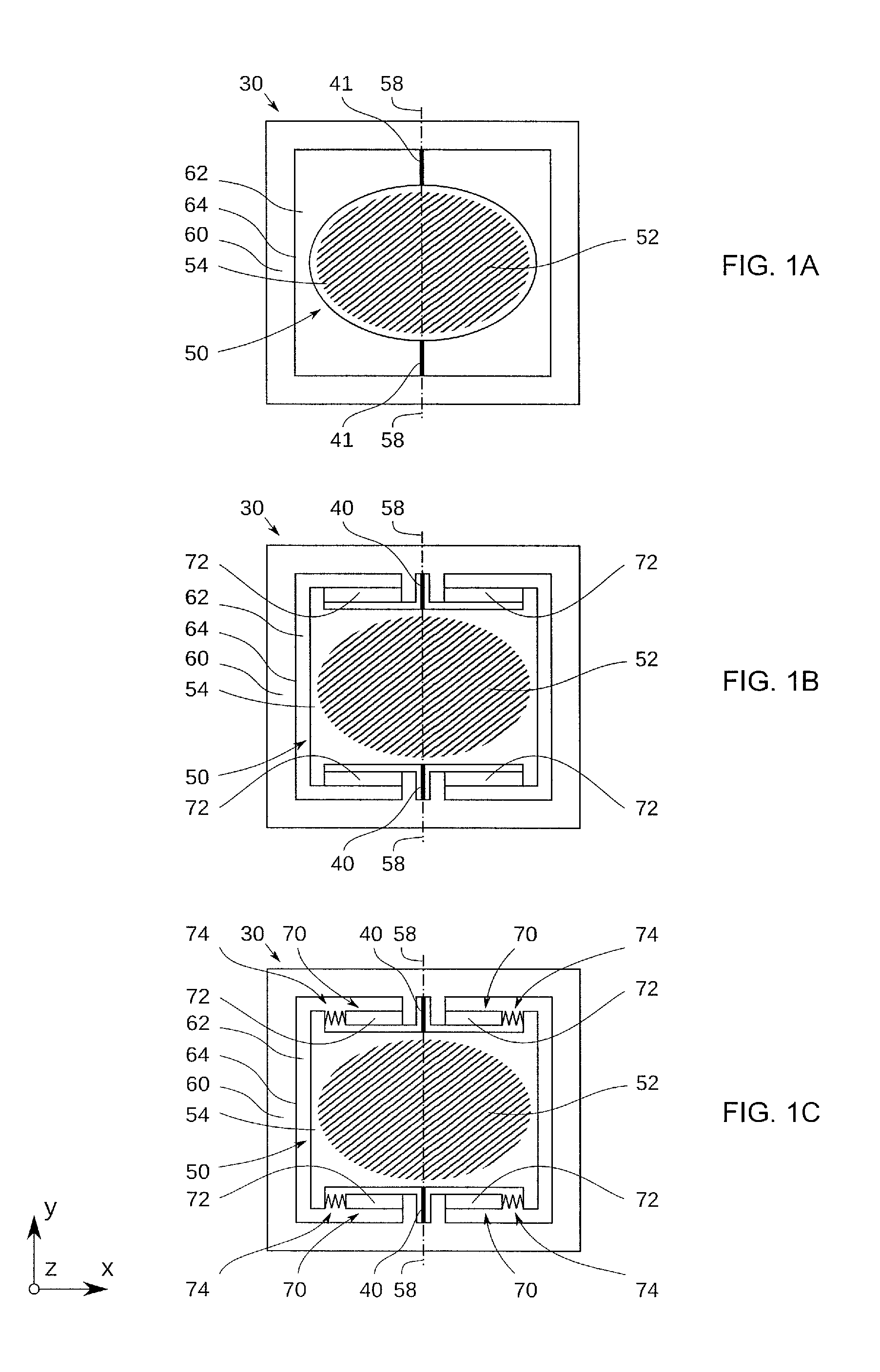
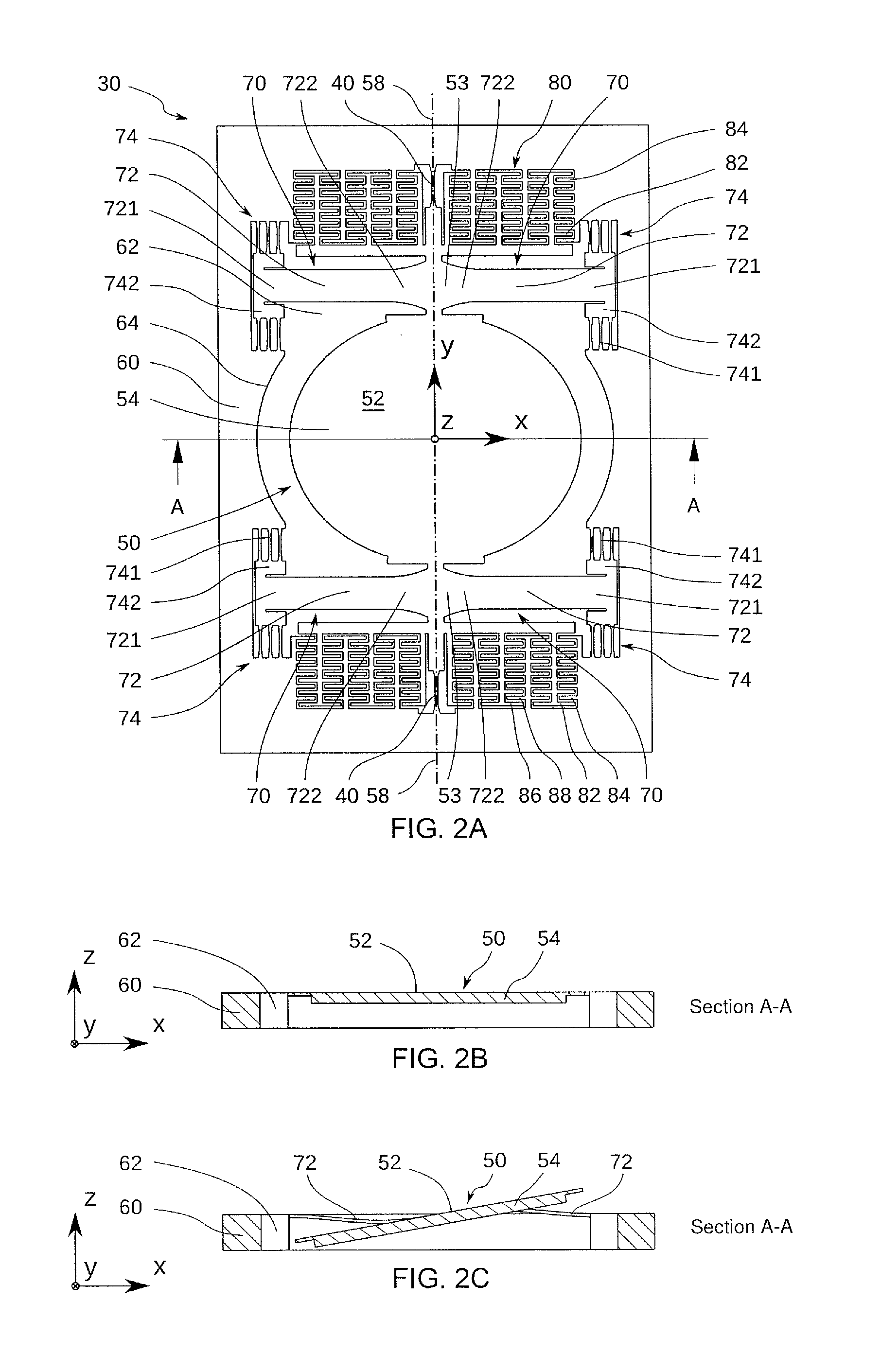
A MEMS micromirror (30) is presented including a frame (60) with a mirror body (50) arranged therein. The mirror body (50) is rotatable around a rotation axis (58) extending in a plane (x-y) defined by the frame (60). The MEMS micromirror (30) further includes at least one cantilever beam assembly (70) having a longitudinal direction and extending within said plane. The MEMS micromirror (30) also includes vertical support beams (40) connected between the mirror body (50) and the frame (60) along the rotation axis (58). The at least one cantilever beam assembly (70) has a cantilever beam (72) with a first and a second end (721, 722) and a relief means (74) at the first end (721) allowing for a translation of the cantilever beam (72) at its first end (721) in said longitudinal direction. The first end (721) is coupled via the relief means (74) to the frame (60) and the second end (722) is fixed to the mirror body (50). The cantilever beam (72) has a thickness, perpendicular to a plane of the frame (60), that is smaller than its width, in the plane of the frame (60).

Description

BACKGROUND[0001]1. Field of the Invention[0002]The technical field of this disclosure is Micro Electro Mechanical Systems (MEMS), particularly, MEMS scanning micromirrors.[0003]2. Related Art[0004]MEMS scanning micromirrors have been developed for the display of visual information. The MEMS scanning micromirror oscillates in one or two dimensions and a laser or other light beam reflects from the mirror surface. Varying the angle and timing of the beam incident on the mirror surface generates a visual image on a screen or other surface, such as a two dimensional display matrix. Different numbers of MEMS scanning micromirrors and lasers are used to produce images of different detail and colors. Exemplary uses for the MEMS scanning micromirrors are video projection (e.g. in head up displays for automotive applications or for pico-projection in mobile phones), optical coherence tomography, and laser Doppler vibrometry.[0005]U.S. Pat. No. 6,392,220 (B1) discloses a monolithically fabrica...

Claims


Application Information

Patent Timeline
Patent Type & Authority Applications(United States)
IPC IPC(8): G02B26/10G02B26/08
CPCG02B26/105G02B26/0841G02B26/0833B81B2203/0163B81B3/007B81B2201/042B81B2203/0109B81B2203/0154
Inventor VAN LIEROP, HENDRIKUS WILHELMUS LEONARDUS ANTONIUS MARIASUIJLEN, MATTHIJS ALEXANDER GERARDVAN OS, MARIJN JOHANNES
Owner INNOLUCE
Learn More