
Triplexer topology

a triplexer and topology technology, applied in the field of communication generally, can solve the problems of high out-of-band impedance, difficult band pass filter design, and low impedance, and achieve the effect of high impedan

Inactive Publication Date: 2014-05-27
MACOM TECH SOLUTIONS HLDG INC
View PDF9 Cites 15 Cited by
  • Summary
  • Abstract
  • Description
  • Claims
  • Application Information

AI Technical Summary

Benefits of technology

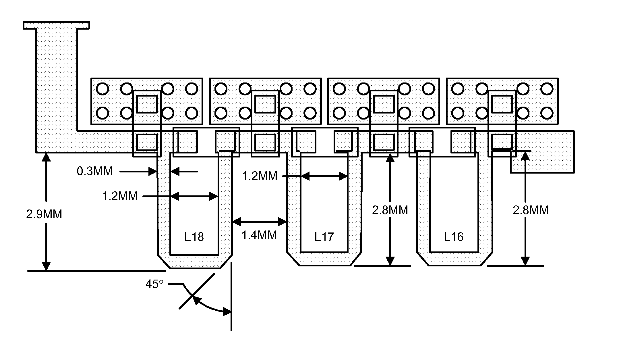
[0004]The objects, features and advantages of the present invention include providing a method and / or apparatus for implementing a novel triplexer topology that may (i) replace a band pass filter with a cascade of high and low pass filters, (ii) provide high and low pass filters that present sufficiently high impedance at respective low and high frequency ends with negligible effect on neighboring filters, (iii) arrange filters on a printed circuit board such that each filter is orthogonal to adjacent filters, (iv) arrange inductors in each filter such that each inductor is orthogonal to adjacent inductors with respect to an axis through the windings of each inductor, and / or (v) implement one or more filter inductors as metal traces on a printed circuit board.

Problems solved by technology

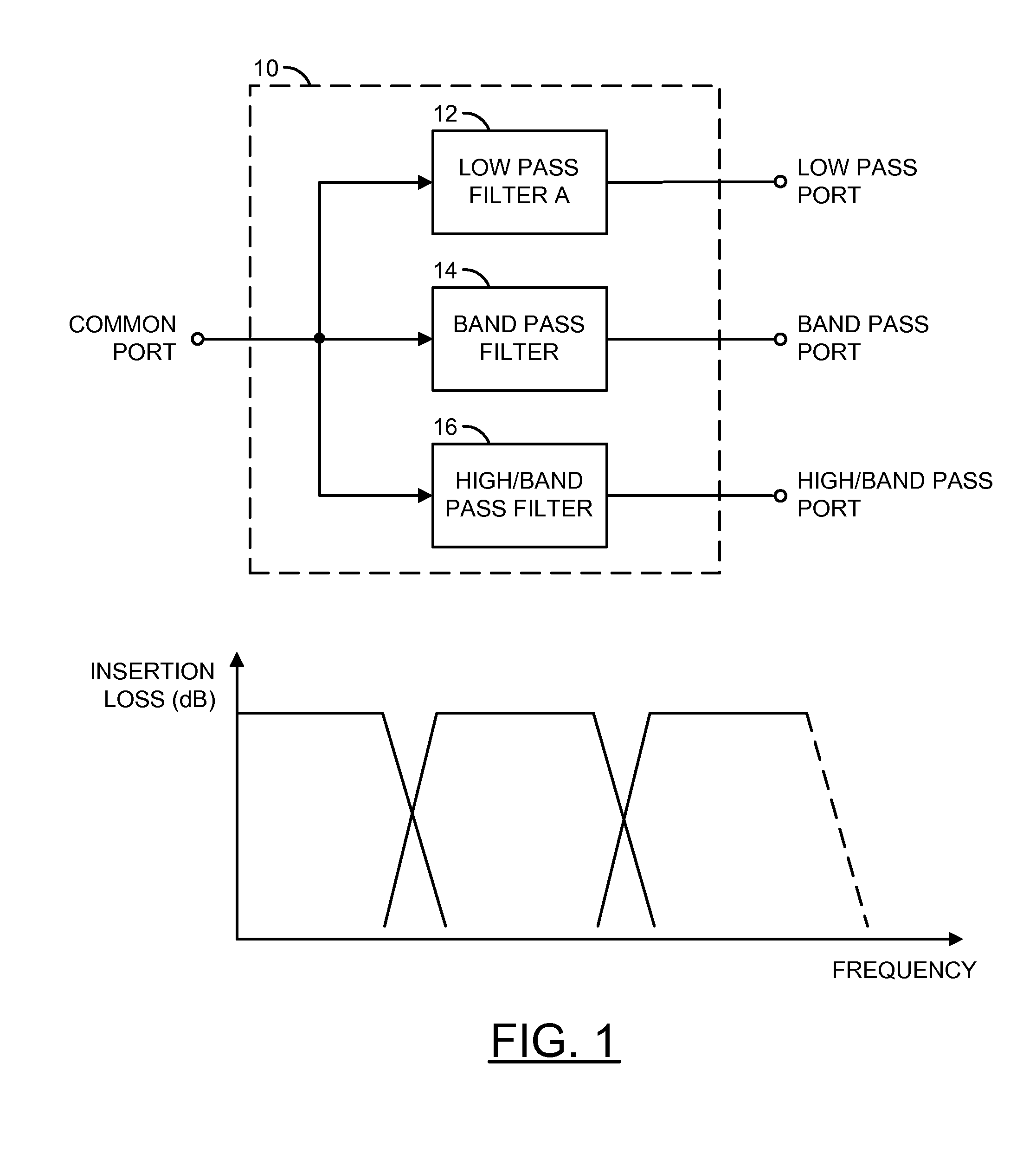
A problem that arises with the standard configuration is difficulty in designing a band pass filter that presents a high out-of-band impedance that has negligible effect on the neighboring filters.
Real world band pass filters have dips in return loss that in turn create an insertion loss dip in neighboring filters.
Also, a complex interaction occurs between the three neighboring filters that makes the overall design very challenging.

Method used


Image

  • Triplexer topology
  • Triplexer topology
  • Triplexer topology

Examples


Embodiment Construction

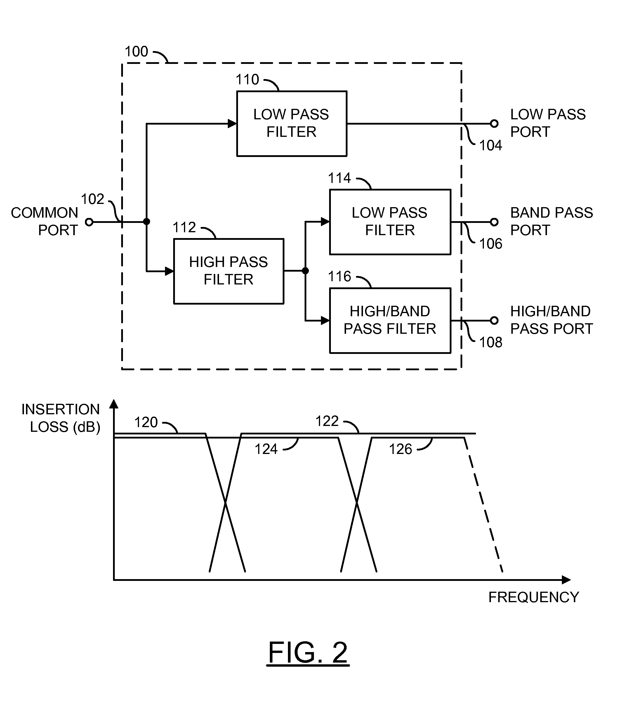
[0014]Referring to FIG. 2, a block diagram of a circuit 100 is shown illustrating an example implementation of a triplexer in accordance with a preferred embodiment of the present invention. The circuit 100 generally provides a triplexer topology that replaces the band pass filter of a standard triplexer with a cascade of high and low pass filters. The cascade of high and low pass filters in accordance with the present invention generally relaxes the design criteria for individual filters. The high pass and low pass filters may present sufficiently high impedance at respective low and high frequency ends with negligible effect on the neighboring filter. The high pass and low pass filters are generally easier to design than a band pass filter that presents high impedance at both out-of-band frequency ends.

[0015]The circuit 100 may have a common port 102 that may receive an input signal, a low pass port 104 that may present a first output signal, a band pass port 106 that may present ...


PUM


Abstract

An apparatus comprising a first filter, a second filter, a third filter, and a fourth filter. The first filter may comprise a low pass filter having a first bandwidth and configured to present a first output signal in response to an input signal received at an input port of the apparatus. The second filter may comprise a high pass filter having a second bandwidth and configured to present a second output signal in response to the input signal received at the input port of the apparatus. The third filter may comprise a low pass filter having a third bandwidth and configured to present a third output signal in response to the second output signal. The fourth filter may comprise a high pass filter having a fourth bandwidth and configured to present a fourth output signal in response to the second output signal.

Description

FIELD OF THE INVENTION[0001]The present invention relates to communications generally and, more particularly, to a method and / or apparatus for implementing a novel triplexer topology.BACKGROUND OF THE INVENTION[0002]Referring to FIG. 1, a block diagram of a standard triplexer 10 is shown. The triplexer 10 has a topology consisting of a low pass filter 12, a band pass filter 14, and a high / band pass filter 16 operating in parallel. All of the filters operate at different frequency bands with often very narrow transition frequency bands. A problem that arises with the standard configuration is difficulty in designing a band pass filter that presents a high out-of-band impedance that has negligible effect on the neighboring filters. Real world band pass filters have dips in return loss that in turn create an insertion loss dip in neighboring filters. Also, a complex interaction occurs between the three neighboring filters that makes the overall design very challenging. Overcoming the p...

Claims


Application Information

Patent Timeline
Patent Type & Authority Patents(United States)
IPC IPC(8): H03H7/46
CPCH03H7/1758H03H2001/0021H03H7/463H03H7/0115H03H7/075H03H7/1766
Inventor SOLSKI, PIOTR M.JONES, STEPHEN P.HAYES, DAVID A.
Owner MACOM TECH SOLUTIONS HLDG INC
Learn More