Beam-adjusting optics

a beam-adjusting and optics technology, applied in the field of optics, can solve the problems of difficult implementation of independent adjustment of the focal spot of each laser, poor optical performance, and high cost of differential micrometers, and achieve the effect of precise positioning of the focus spo

Active Publication Date: 2010-08-31
BECTON DICKINSON & CO
View PDF12 Cites 16 Cited by
  • Summary
  • Abstract
  • Description
  • Claims
  • Application Information

AI Technical Summary

Benefits of technology

[0008]The present invention provides illumination optics for use in an optical analyzer that includes a light source, such as a laser or other source, adapted to emit a collimated, or approximately collimated, beam, a focusing lens that focuses the beam onto a focus spot, and beam-adjusting optics positioned in the light path between the light beam source and the focusing lens, which allow for precise positioning of the focus spot of the focused light beam. The beam-adjusting optics of the present invention comprises at least one movable focusing lens, mounted in a positioning device that allows repositioning of the lens in a plane perpendicular to the light path. The size of the movable focusing lens will be sufficiently larger than the width of the collimated beam such that the beam passes through the movable lens when the lens is repositioned.
[0011]Increasing the focal length of the movable beam-adjusting lens decreases the sensitivity of the focus spot positioning to changes in the position of the beam-adjusting lens, i.e., increasing the focal length of the movable beam-adjusting lens will decrease the displacement of the focus spot in the sample detection region for a given displacement of the beam-adjusting lens. The decreased sensitivity to movement of the movable beam-adjusting lens allows the use of less expensive, less precise lens positioning mechanisms, such as simple screw-type positioning systems, to obtain precise positioning control over the beam focus spot. As general guidance, the focal length of the movable beam-adjusting lens, minus the distance between the movable beam-adjusting lens and the focusing lens, preferably is at least two times as long as the focal length of the focusing lens, more preferably at least four times as long, and even more preferably, at least six times as long.
[0013]In another embodiment, the beam-adjusting optics of the present invention comprise a converging lens having a positive focal length (e.g., a convex lens) and a diverging lens having a negative focal length (e.g., a concave lens), located a short distance apart other along the optical path and positioned in the optical path such that the optical axis of each lens is parallel to the optical path. At least one of the converging lens and diverging lens is mounted in a positioning device such that the lens can be moved in a plane perpendicular to the optical path, and functions as the beam-adjusting lens. The width of the beam-adjusting length lens is sufficiently larger than the width of the excitation beam to allow for movement of the lens in a plane perpendicular to the optical path while remaining in the optical path. The use of a converging lens along with a diverging lens enables significantly increasing the equivalent focal length of the beam-adjusting optics, which minimizes the effect of the lens pair on the effective focal length of the illumination optics, but which has minimal effect on the beam-adjusting property of the beam-adjusting lens.
[0015]In a preferred embodiment, the plano-concave lens and the plano-convex lens are matched, i.e., the focal lengths of the lenses are of the same magnitude, but of opposite sign, and the distance between the lens is small, such that parallel light beams entering the beam adjustment optics will exit the beam adjustment optics almost parallel. In this embodiment, the equivalent focal length of the lens pair is much longer than the focal length of the individual lenses, and the lens pair has a negligible effect on the effective focal length of the illumination optics.
[0017]The beam-adjusting optics of the present invention are particularly suited for use in the illumination light optics of a multi-laser optical analyzer. As the beam adjustment optics can be located anywhere before the focusing lens, individual beam-adjusting optics can be used for each of the lasers in a multi-laser system, thus enabling independent adjustment of the focal spot for each of the lasers.

Problems solved by technology

Optimal performance is compromised if the focused light beam is not properly adjusted on the core stream, and flow cytometers typically include one or more devices for adjusting the positioning of the focused light beam on the core stream.
Conventional positioning methods typically employ expensive differential micrometers to position the light source itself or optical elements, such as mirrors or prisms.
One disadvantage of this typical implementation is that independent adjustment of the focal spot of each laser is not easily implemented.

Method used


Image

  • Beam-adjusting optics
  • Beam-adjusting optics
  • Beam-adjusting optics

Examples


Embodiment Construction

[0023]The following definitions are provided for clarity. Unless otherwise indicated, all terms are used as is common in the art. All reference cited herein, both supra and infra, are incorporated herein by reference.

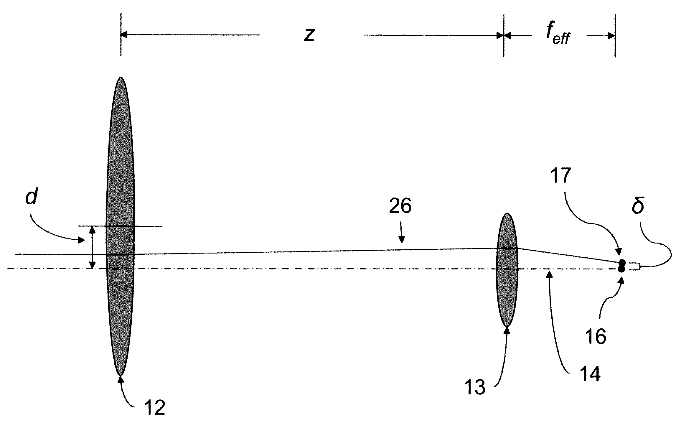
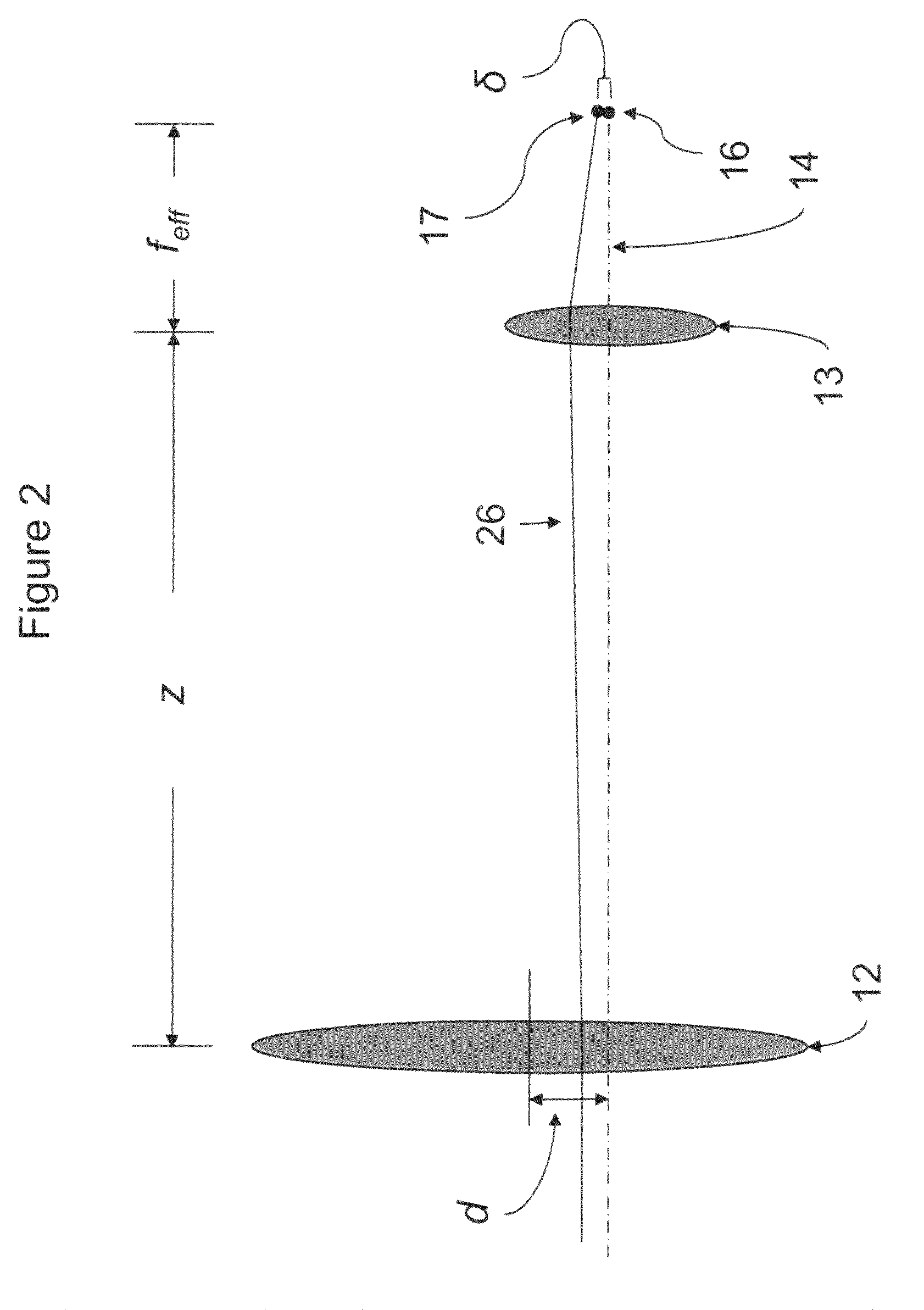
[0024]As used herein, the “equivalent focal length” or “combined focal length” of a compound optical system refers to the focal length of a compound optical system, given as if it were a single optical element. The equivalent focal length is the distance from the secondary principle point of the compound optical system to the focal point. The equivalent focal length, feq, for a combination of two components is related to the focal lengths of the two components by the following equation:

[0025]feq=f1·f2f1+f2-d,(1)

wherein f1 and f2 are the focal lengths of the individual components and the d is the distance between the components. The equivalent focal length of a optical system containing more that two components can be calculated by first calculating the equivalent focal ...


PUM

PropertyMeasurementUnit
optical analyzeraaaaaaaaaa
focal length f1aaaaaaaaaa
focal length f2aaaaaaaaaa

Abstract

The present invention provides an optical analyzer having illumination optics that include a light source, such as a laser or other source, adapted to emit a collimated, or approximately collimated, light beam, a focusing lens that focuses the beam onto a focus spot within a detection region, and beam-adjusting optics positioned in the light path between the light beam source and the focusing lens, which allow for precise positioning of the focus spot within the detection region. The beam-adjusting optics of the present invention comprise at least one movable focusing lens, mounted in a positioning device that allows repositioning of the lens in a plane perpendicular to the light path.

Description

CROSS-REFERENCE TO RELATED APPLICATIONS[0001]The present application claims priority to U.S. provisional application Ser. No. 60 / 993,758, filed Sep. 14, 2007, which is incorporated herein by reference in its entirety.BACKGROUND OF THE INVENTION[0002]1. Field of the Invention[0003]The present invention relates to the field of optics and, in particular, to laser optics, as used in optical analyzers.[0004]2. Description of Related Art[0005]Particle analyzers, such as flow and scanning cytometers, are well known analytical tools that enable the characterization of particles on the basis of optical parameters such as light scatter and fluorescence. In a flow cytometer, for example, particles, such as molecules, analyte-bound beads, or individual cells, in a fluid suspension are passed by a detection region in which the particles are exposed to an excitation light, typically from one or more lasers, and the light scattering and fluorescence properties of the particles are measured. Partic...

Claims


Application Information

Patent Timeline
Patent Type & Authority Patents(United States)
IPC IPC(8): G02B9/04G01N21/00G02B27/64G02B9/12
CPCG01N15/1434G01N15/1459G02B7/08G01N2015/1452
Inventor CHEN, YONG QIN
Owner BECTON DICKINSON & CO
Why Eureka
Try Eureka