Apparatus and method for cooling random-access (RAM) modules

Inactive Publication Date: 2014-10-09
PARKER-HANNIFIN CORP
View PDF18 Cites 9 Cited by
  • Summary
  • Abstract
  • Description
  • Claims
  • Application Information

AI Technical Summary

Benefits of technology

[0011]Preferably, the clip or clips are easily slipped off individually

Problems solved by technology

Oftentimes the cooling requirements exceed the availa

Method used


Image

  • Apparatus and method for cooling random-access (RAM) modules
  • Apparatus and method for cooling random-access (RAM) modules
  • Apparatus and method for cooling random-access (RAM) modules

Examples


Example

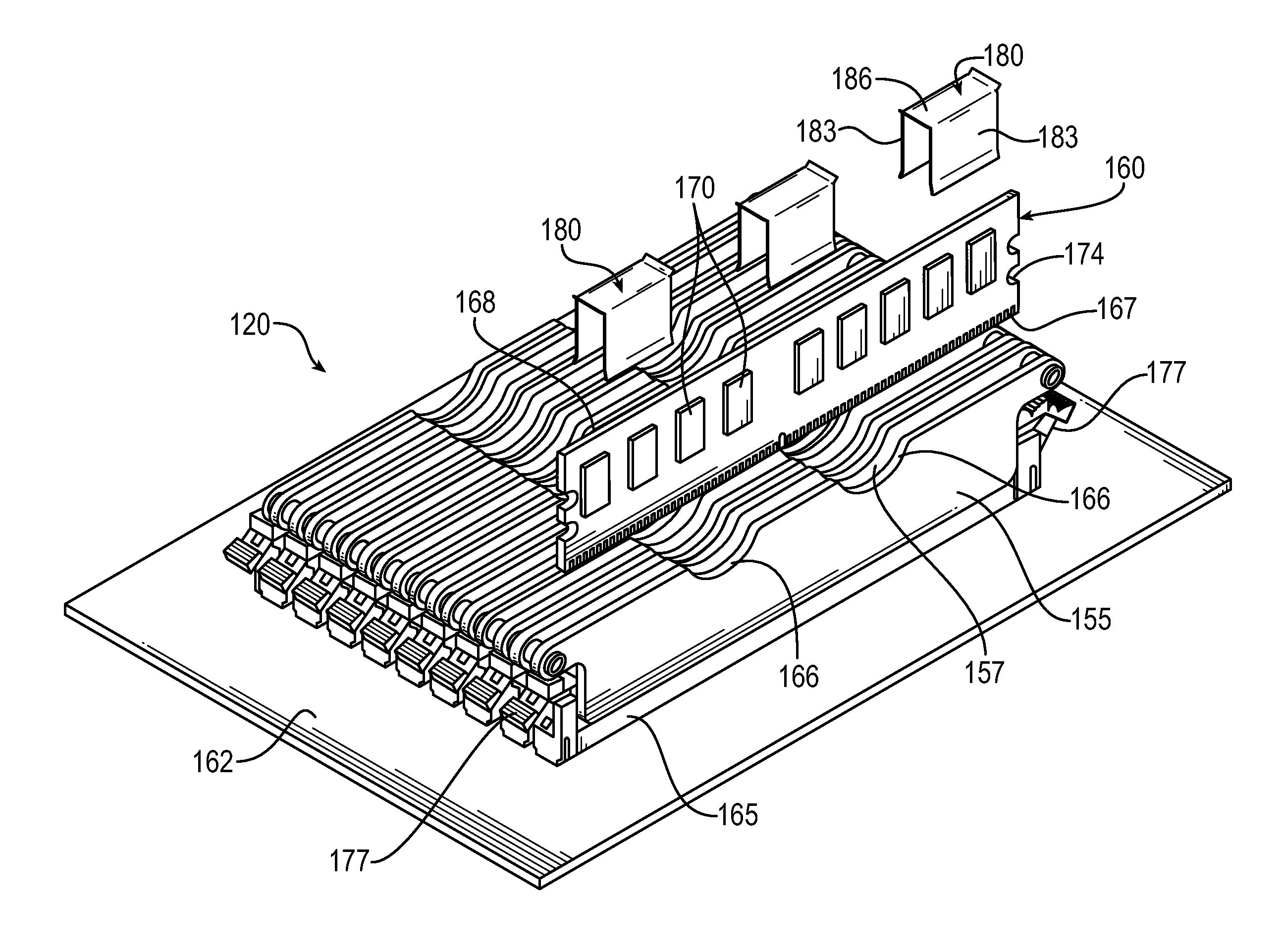
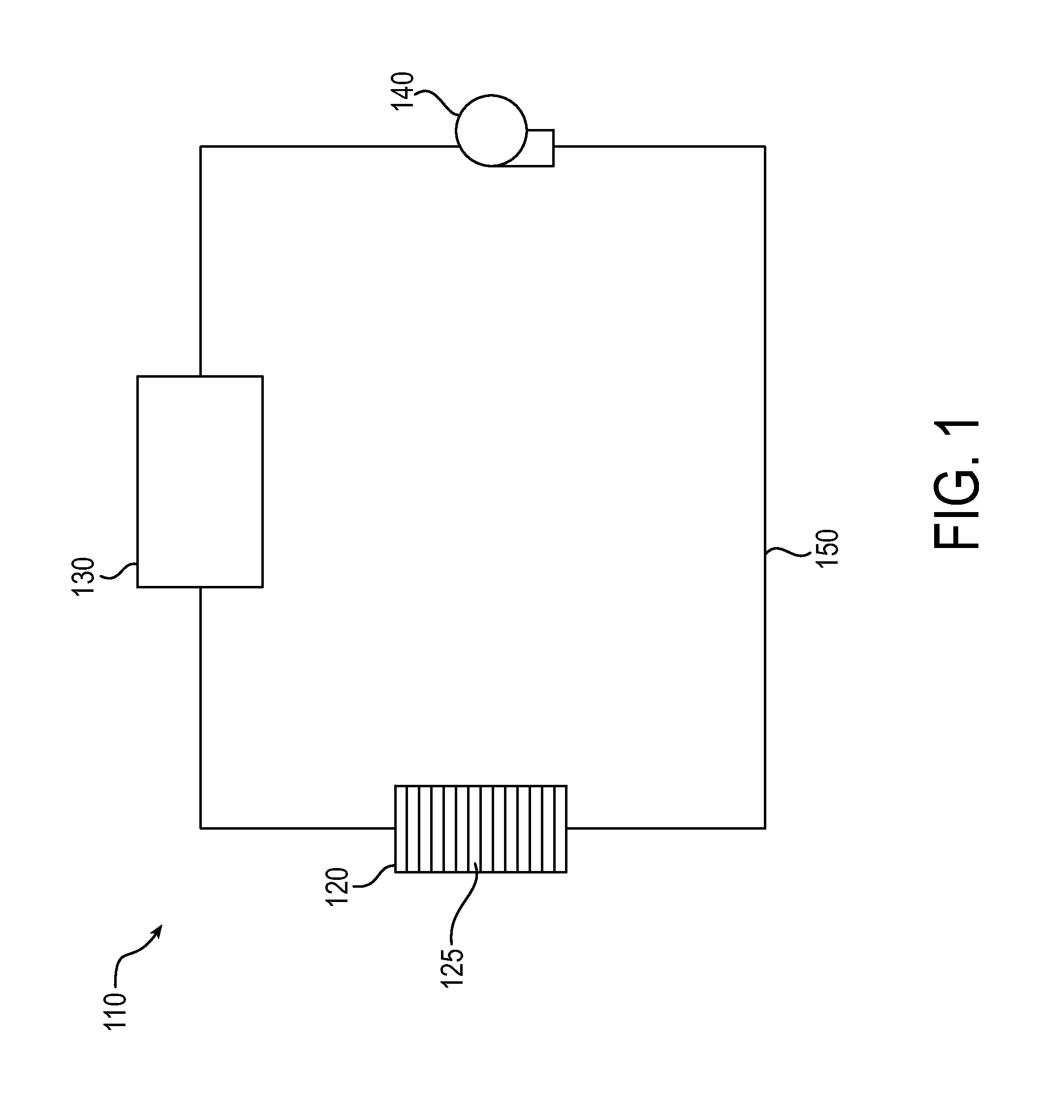
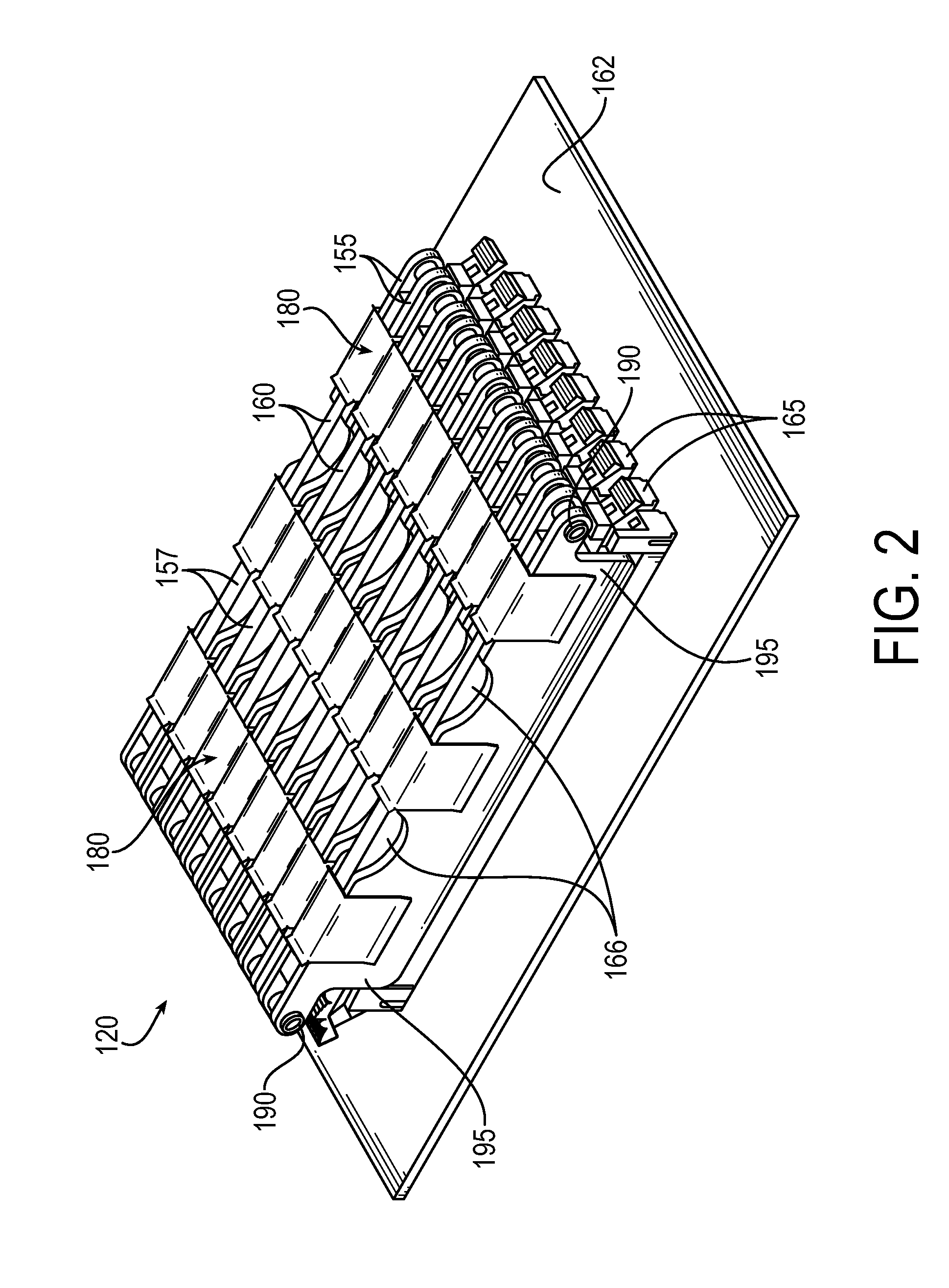
[0037]Referring to FIG. 1, a pumped liquid multiphase cooling system 110 is shown. The system 110 includes a cooling module / apparatus 120 as described in more detail below that is in thermal contact with one or more electronic modules 125 (more particularly electronic components of such modules), a heat exchanger 130 for removing heat from the system, and a pump 140 for circulating a cooling media through the system, all of which are connected to each other by fluid circuit conduits 150 to form a fluid cooling circuit 135. A fluid such as water or a refrigerant is pumped through the system 110 to cool the electronic components 125. The heat generated by the electronic component 125 is transferred to the fluid, which may cause the fluid to partially vaporize. The fluid then travels to the heat exchanger 130 wherein the heat is rejected from the system 110 and the fluid returns to the cooling module 120 by way of the pump 140. As will be appreciated, the cooling system may be a multip...


PUM


Abstract

An electronic module cooling apparatus and method for cooling a plurality of electronic modules each including a circuit board to which one or more electronic components are mounted, in particular memory modules, disposed on a substrate in spaced-apart parallel relationship. The apparatus and method provide for effective cooling of the electronic modules while still allowing for insertion and removal of the electronic modules from a common substrate and/or providing for biased contact with electrical components of the electronic modules. In a particular embodiment, the apparatus provides for liquid cooling memory boards, allowing heat to be removed from the electronic components that are contained in densely populated enclosures without the need for air flow.

Description

TECHNICAL FIELD[0001]The present invention relates to thermal management of electronic circuit modules, for example, liquid cooling of random-access memory modules.BACKGROUND[0002]Electronic circuit modules are often mounted in one or more rows in a chassis or other enclosure. The modules usually consist of a circuit board to which one or more electronic components are mounted. The modules typically are mounted perpendicular to a planar mounting substrate by card edge connectors that are electrically and / or mechanically connected to mating connectors on the mounting substrate. The cards are usually spaced apart to allow air to flow between the cards for cooling the cards, i.e. removing heat that is generated by electrical components of the modules.[0003]Electronic systems using circuit modules are continually being reduced in size while the heat generated by the electronic modules is increasing. Oftentimes the cooling requirements exceed the available capacity of natural or forced c...

Claims


Application Information

Patent Timeline
IPC IPC(8): G06F1/20
CPCG06F1/185G06F2200/201H05K7/20254G06F1/20
Inventor LOUVAR, TIMOTHY DOUGLASHUNNICUTT, JESSICA ANNE
Owner PARKER-HANNIFIN CORP
Why Eureka
Try Eureka