Supercharge Your Innovation With Domain-Expert AI Agents!

Rf-safe interventional or non-interventional instrument for use in an MRI apparatus

a non-interventional, interventional technology, applied in the direction of instruments, magnetic variable regulation, process and machine control, etc., can solve the problems that trap circuits or chokes used to suppress resonant rf currents on conductors cannot be safely and efficiently used outside the examination object, and achieves the effect of reducing the risk of rf-safety, and compromising the function nor efficiency

Active Publication Date: 2014-10-09
KONINKLJIJKE PHILIPS NV
View PDF6 Cites 2 Cited by
  • Summary
  • Abstract
  • Description
  • Claims
  • Application Information

AI Technical Summary

Benefits of technology

The patent is about a way to prevent RF resonances (which are electrical currents that can cause danger) from occurring on long conductors in a laboratory setting. These resonances can be caused by conductor loops that occur when using the instrument. The invention uses a trap circuit to keep the instrument's signal processing and other remote units decoupled from the distal conductor, which can have a resonance. This results in safer RF practices in the laboratory.

Problems solved by technology

Further, the above and other known solutions for providing RF-safety are often not suitable for use in connection with very thin instruments likes those which are to be introduced into an examination object.
For example, trap circuits or RF chokes which are used for suppressing resonant RF currents on a conductor can only be used safely and efficiently outside an examination object due to their dimensions and due to a potential heating at the traps themselves.
All this poses the general problem that such (distal) conductors which are to be introduced into an examination object (e.g. of those interventional instruments which are provided for MR guided vascular interventions) can become resonant themselves, so that the examination object is subject to an RF heating.

Method used


Image

  • Rf-safe interventional or non-interventional instrument for use in an MRI apparatus
  • Rf-safe interventional or non-interventional instrument for use in an MRI apparatus
  • Rf-safe interventional or non-interventional instrument for use in an MRI apparatus

Examples


first embodiment

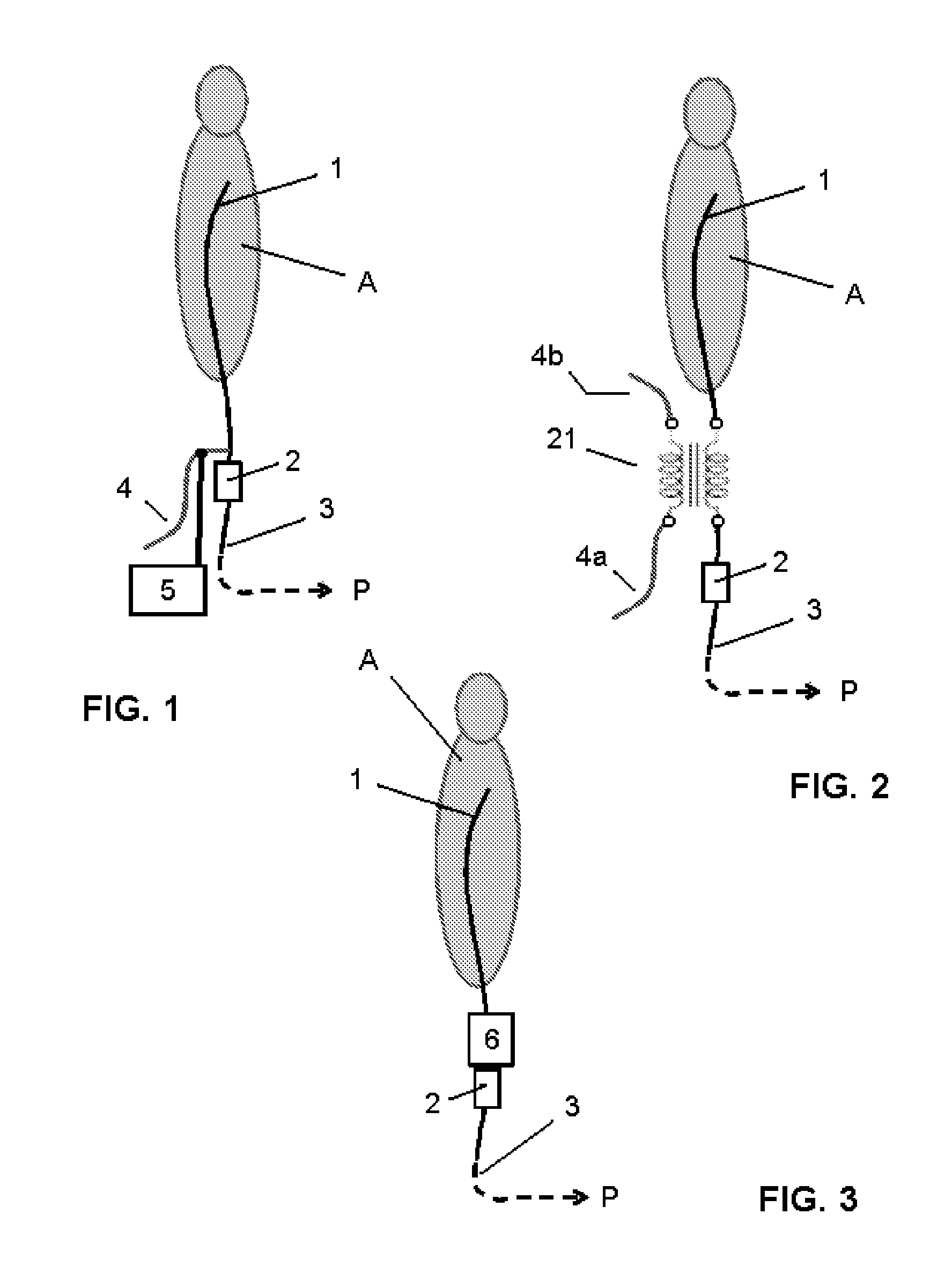
[0043]FIG. 1 shows a basic set-up of an interventional instrument according to the invention. Further, FIG. 1 schematically shows an examination object A in the form of a patient.

[0044]The interventional instrument substantially comprises a first conductive element 1 at a distal part or section of the instrument (in the following “distal conductor”) which is at least partly to be introduced into the examination object A. The distal conductor 1 comprises a distal end which is electrically open for RF common mode currents, and a proximal end which is connected preferably via an RF trap circuit like an RF choke 2 to a distal end of a second conductive element 3 at a proximal part or section of the instrument (in the following “proximal conductor”) which connects the interventional instrument with related operating units, control units or power supply units P (not indicated) at its proximal end and is realized e.g. in the form of an RF transmission line or cable.

[0045]Further, FIG. 1 sh...

second embodiment

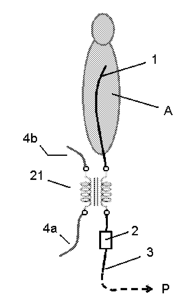
[0055]FIG. 2 shows a basic set-up of an interventional instrument according to the invention together with an examination object A.

[0056]The same or corresponding components or elements as in FIG. 1 are denoted with the same or corresponding reference numbers.

[0057]The basic difference between this second embodiment and the first embodiment is, that the damping element is effectively added to the distal conductor 1 by an inductive coupling which is realized exemplarily by means of a transformer 21. The transformer 21 comprises a first winding which is serially connected into the distal conductor 1 and a second winding with which the damping element 4a, 4b is connected. The damping element is realized in the form of a first wire extension 4a and a second wire extension 4b, wherein the first wire extension 4a is connected with one end of the second winding and the second wire extension 4b is connected with the other end of the second winding of the transformer 21. The first and the se...

third embodiment

[0059]FIG. 3 shows a basic set-up of an interventional instrument according to the invention together with an examination object A.

[0060]The same or corresponding components or elements as in FIGS. 1 and 2 are denoted with the same reference numbers.

[0061]The interventional instrument again comprises a distal conductor 1 which is to be introduced into the examination object A, and a proximal conductor 3 in the form of a RF transmission line or cable which connects the interventional instrument with related operating units, control units or power supply units P (not indicated). The basic difference between this third embodiment and first and the second embodiment is that according to the third embodiment an electrically damping element in the form of at least one lossy dielectric load 6 is provided instead of a resistive and / or a reactive load 4; 4a, 4b. It is again effectively added to the distal conductor 1 at a position of the distal conductor 1 of an increased or maximum of the R...


PUM


Abstract

An RF-safe interventional or a non-interventional instrument is disclosed for use during an MR imaging or MR examination of an examination object (A), which instrument is made of or comprises at least one longitudinal or elongated electrically conductive element (1, 3), especially in the form of a conductor or wire or line for feeding electrical signals, or in the form of the instrument itself or a component or a part thereof, which is not provided for feeding electrical signals but nevertheless electrically conductive, wherein all such elements are subject to RF common mode currents which are induced in the element when the instrument or element is exposed to an RF / MR excitation field generated during MR imaging or MR examination by means of an MR imaging apparatus. The instrument is made RF-safe by increasing the energy A loss of an oscillator which is represented by the conductor (1, 3) by means of a damping element (4; 6) in order to prevent or limit RF heating of the examination object (A) at or surrounding the conductor (1, 3).

Description

FIELD OF THE INVENTION[0001]The invention relates to an RF-safe interventional or a non-interventional instrument for use during an MR imaging or MR examination of an examination object, which instrument is made of or comprises at least one longitudinal or elongated electrically conductive element, especially in the form of a conductor or wire or line for feeding electrical signals, or in the form of the instrument itself or a component or a part thereof, which is not provided for feeding electrical signals but nevertheless electrically conductive, wherein all such elements (“conductors”) are subject to RF common mode currents which are induced in the element when the instrument or element is exposed to an RF / MR excitation field generated during MR imaging or MR examination by means of an MR imaging apparatus.[0002]Such instruments and components or parts, respectively, are for example catheters, probes, surgical devices, biopsy or puncture needles, pointers, implants, wire-braided ...

Claims


Application Information

Patent Timeline
Patent Type & Authority Applications(United States)
IPC IPC(8): G01R33/28A61B90/00
CPCG01R33/288
Inventor WEISS, STEFFENLIPS, OLIVERDAVID, BERND
Owner KONINKLJIJKE PHILIPS NV
Features
  • R&D
  • Intellectual Property
  • Life Sciences
  • Materials
  • Tech Scout
  • Unparalleled Data Quality
  • Higher Quality Content
  • 60% Fewer Hallucinations
Learn More