
Electronic device using data theft protection

a technology of electronic devices and data theft protection, applied in the direction of instruments, power supply for data processing, liquid/fluent solid measurement, etc., can solve problems such as tragic consequences

Active Publication Date: 2014-10-09
CLOUD NETWORK TECH SINGAPORE PTE LTD
View PDF8 Cites 6 Cited by
  • Summary
  • Abstract
  • Description
  • Claims
  • Application Information

AI Technical Summary

Benefits of technology

The patent text describes an electronic device that uses data theft protection with multiple electrical signal interfaces. The device includes a printed circuit board with a copper foil and a detecting unit. The copper foil has a first via and a plurality of electrical signal interfaces surrounding it. The electrical signal interfaces are general purpose input output ports (GPIOs) that are connected to a logic level generator. The logic level generator generates a logic 1 signal. The device also includes a logic level port and an output port for each GPIO. The device is designed to prevent data theft and protect against disassembly.

Problems solved by technology

Important data is stored in a data circuits of electronic devices, and if the data is lost, consequences could be tragic.
Therefore, it is a big challenge to provide an electronic device which can be protected against data theft by disassembly.

Method used


Image

  • Electronic device using data theft protection
  • Electronic device using data theft protection
  • Electronic device using data theft protection

Examples


Embodiment Construction

[0011]The disclosure is illustrated by way of example and not by way of limitation in the figures of the accompanying drawings in which like references indicate similar elements. It should be noted that references to “an” or “one” embodiment in this disclosure are not necessarily to the same embodiment, and such references can mean “at least one.”

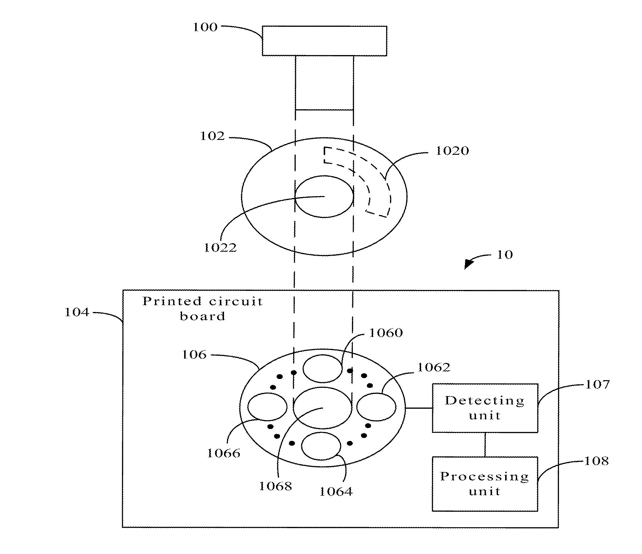
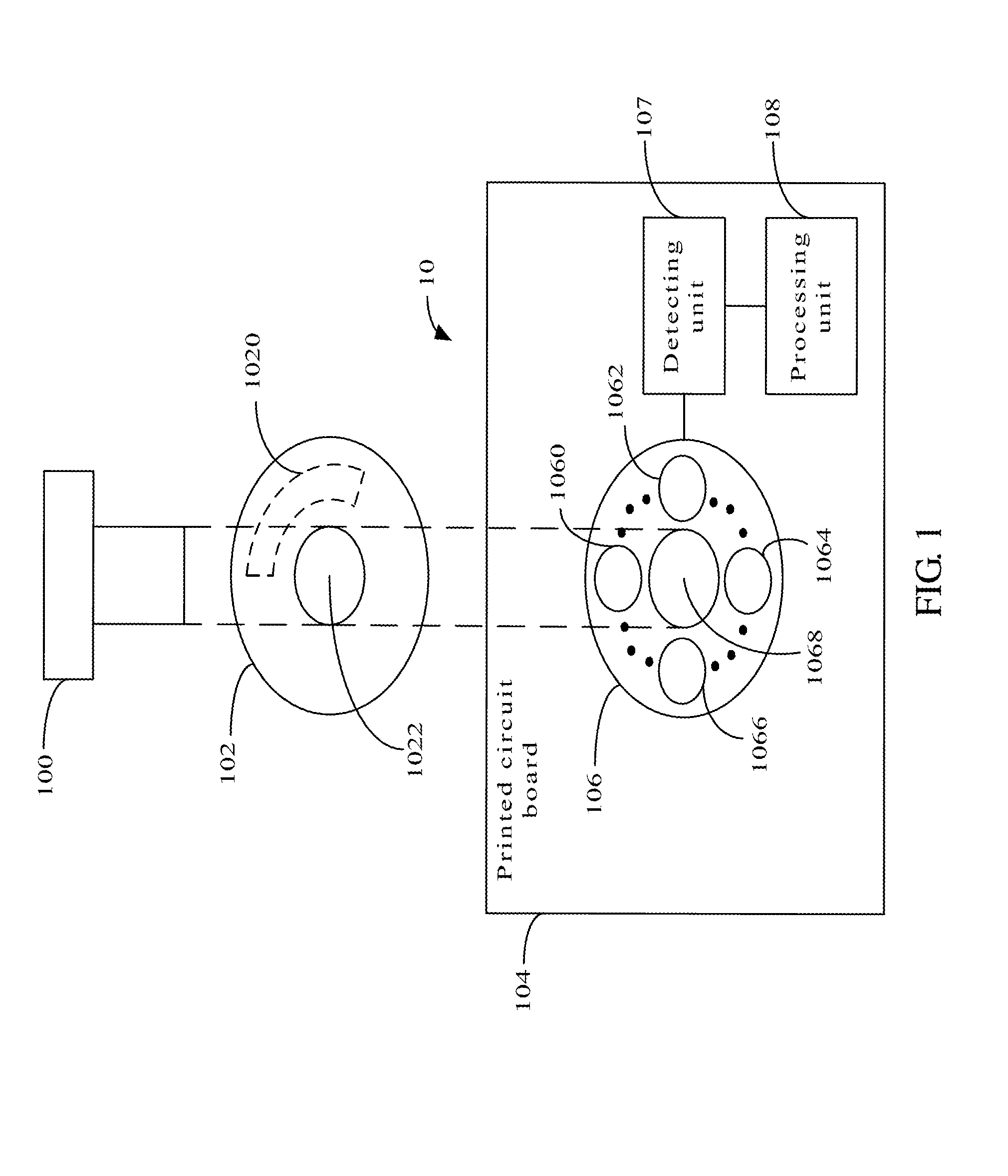
[0012]FIG. 1 is a diagram of one embodiment of an electronic device 10. The electronic device 10 includes a screw 100, a washer 102 and a printed circuit board 104. The printed circuit board 104 includes a copper foil 106, a detecting unit 107, and a processing unit 108.

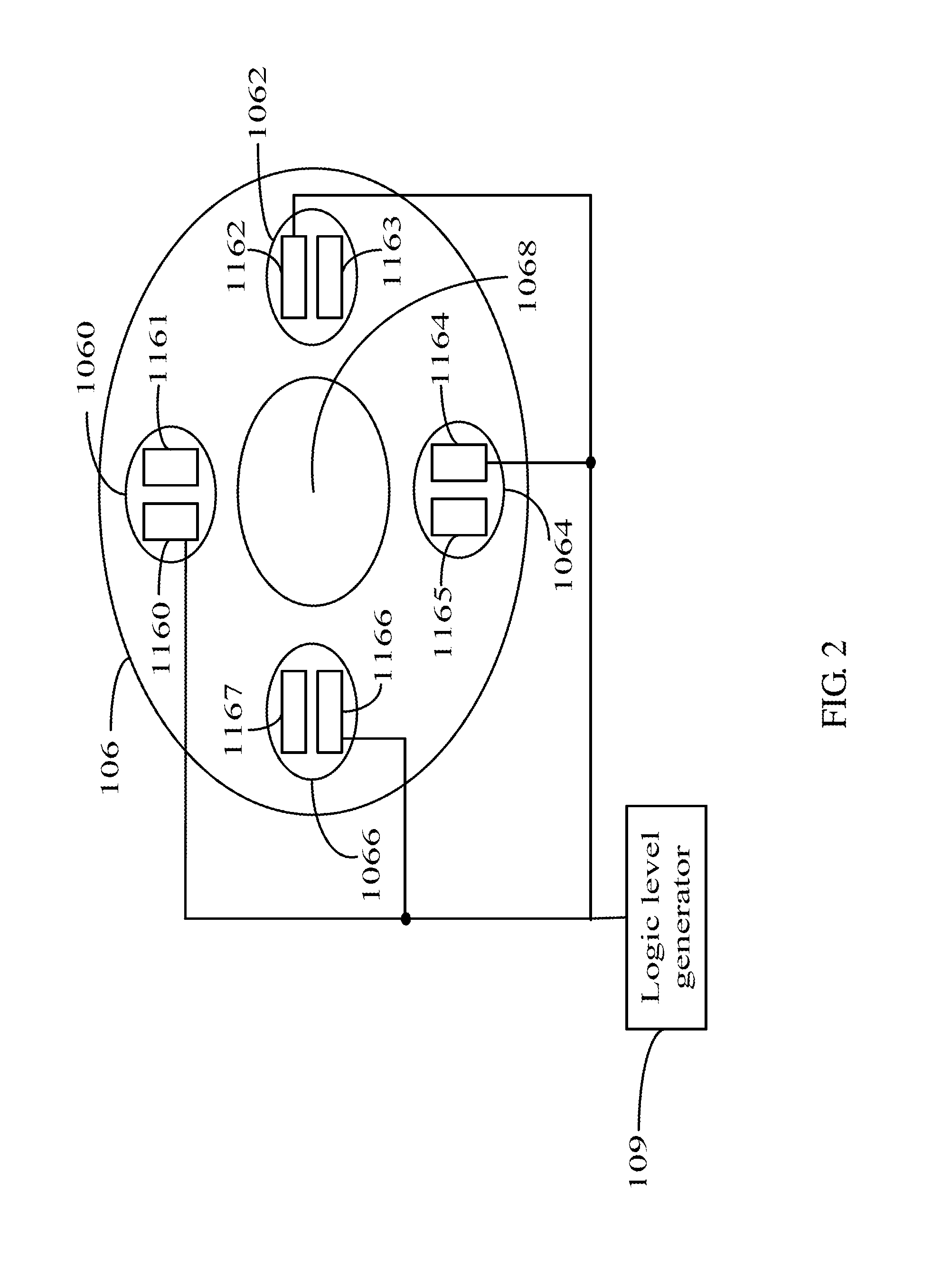
[0013]FIG. 2 is a top view of a copper foil 106 of one embodiment of the electronic device 10 of FIG. 1. A middle of the copper foil 106 defines a first via 1068 that passes through the screw 100. A top of the copper foil 106 defines a plurality of electrical signal interfaces surrounds the first via 1068. In one embodiment, the electrical signal interfaces are general purpo...


PUM


Abstract

An electronic device includes a washer, a printed circuit board, and a screw. The printed circuit board includes a copper foil, a detecting unit and a processing unit. The copper foil comprises a plurality of electrical signal interfaces surrounding a first via defined in the copper foil. The washer defines a second via and includes a transmission metal. The screw combines the printed circuit board and the washer through the second via and the first via. The detecting unit stores an original logic level signal, and detects logic level signals of the electrical signal interfaces in real-time. The processing unit compares the original logic level signal and the detected logic level signal, to determine whether the electronic device is disassembled. If the electronic device is disassembled, the electronic device stops working.

Description

BACKGROUND[0001]1. Technical Field[0002]The disclosure relates to electronic devices, and particularly to an electronic device using data theft protection with a plurality of electrical signal interfaces.[0003]2. Description of Related Art[0004]Important data is stored in a data circuits of electronic devices, and if the data is lost, consequences could be tragic. To obtain the data, the electronic devices is often disassembled. Therefore, it is a big challenge to provide an electronic device which can be protected against data theft by disassembly.BRIEF DESCRIPTION OF THE DRAWINGS[0005]Many aspects of the present embodiments can be better understood with reference to the following drawings. The components in the drawings are not necessarily drawn to scale, the emphasis instead being placed upon clearly illustrating the principles of the present embodiments. Moreover, in the drawings, all the views are schematic, and like reference numerals designate corresponding parts throughout t...

Claims


Application Information

Patent Timeline
IPC IPC(8): G06F21/88
CPCG06F21/88G06F21/86
Inventor WU, CHI-HSINCHUANG, MAO-CHANG
Owner CLOUD NETWORK TECH SINGAPORE PTE LTD
Learn More