Structure of Heel Counter

Inactive Publication Date: 2014-10-16
YEH TORNG HAUR
View PDF10 Cites 41 Cited by
  • Summary
  • Abstract
  • Description
  • Claims
  • Application Information

AI Technical Summary

Benefits of technology

[0011]To solve the drawbacks of the heel counter in the prior art, the disclosed heel counter is roughly a U-shaped cup, whose rim has several hollow parts to reduce the hardness thereof, to improve comfort by providing appropriate elasticity, and to c

Problems solved by technology

Although the heel counter provides protection, the air circulation around the heel is hindered because there is no hollow part.
Such a plastic reduces the comfort of the shoes.
Moreover, althoug

Method used


Image

  • Structure of Heel Counter
  • Structure of Heel Counter

Examples


Example

[0017]The present invention will be apparent from the following detailed description, which proceeds with reference to the accompanying drawings, wherein the same references relate to the same elements.

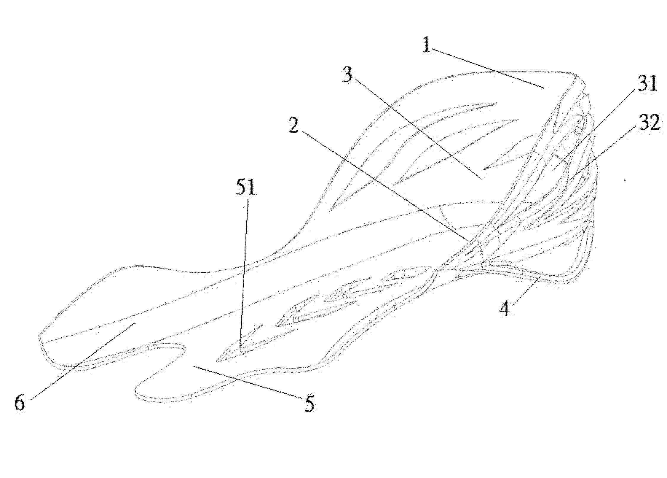
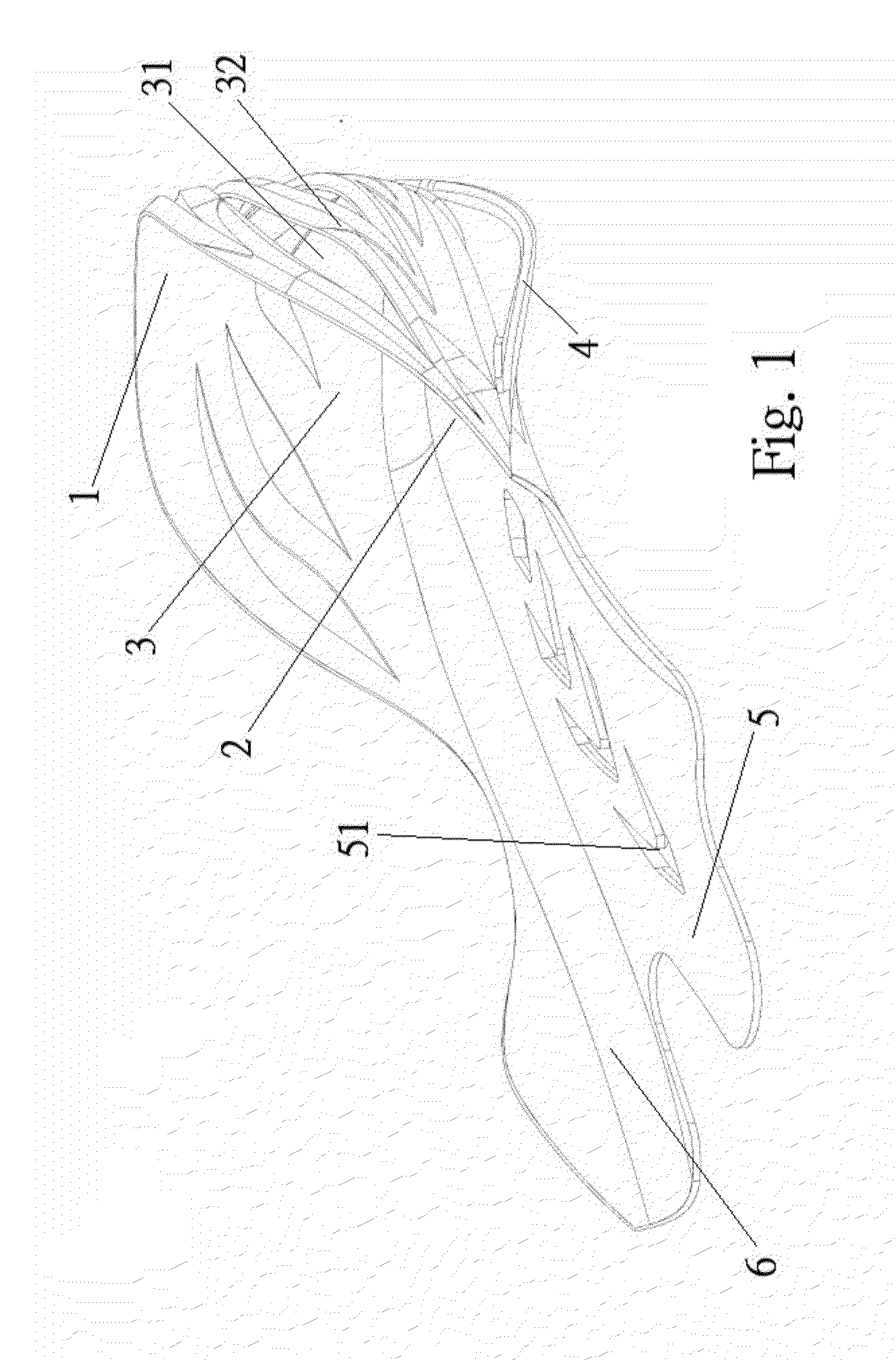
[0018]Please refer to FIG. 1. Similar to the heel counter in the prior art, the invention is roughly a U-shaped cup 1. The cup bottom is a support part 2 to distribute pressure on the heel. The cup rim 3 with a narrow upper part and a wider lower part embraces the surrounding of the heel to provide protection and stability.

[0019]The invention differs from the prior art in that the cup rim 3 has several hollow parts 31 to reduce the overall hardness, to improve comfort by providing appropriate elasticity, and to circulate air.

[0020]The invention differs from the prior art in that the bottom surface of the support part 2 has an arc-shaped supporting elastic plate 4 to better absorb shocks on the heel and alleviate pressure.

[0021]The invention differs from the prior art in that the cup b...


PUM

PropertyMeasurementUnit
Pressureaaaaaaaaaa
Elasticityaaaaaaaaaa
Stabilityaaaaaaaaaa

Abstract

A heel counter is roughly a U-shaped cup. The bottom of the cup is a support part with the effect of uniformly distributing pressure on the heel. The cup rim embraces the surrounding of the heel to provide protection and stability. The cup rim has several hollow parts to reduce the overall hardness, to enhance comfort by providing suitable elasticity, and to circulate air. The bottom surface of the support part of the cup is provided with arc-shaped supporting elastic plate to alleviate pressure on the heel by absorbing shocks. A midfoot and phalanx support part is formed from the cup bottom toward the midfoot. A lateral longitudinal arc support part is formed from the outer side of the cup bottom toward the midfoot.

Description

BACKGROUND OF THE INVENTION[0001]1. Field of Invention[0002]The invention relates to a shoe and, in particular, to an improved heel counter.[0003]2. Related Art[0004]To avoid a sprained ankle due to the sideway motion of the show heel and to prevent vertical motion of the shoe heel due to deformation, the shoe heel is often installed with a hard protector called the heel counter. It is used to fix the shoe heel. The counter is particularly important for motion control shoes.[0005]The structure of a typical heel counter has been detailed in U.S. Pat. No. 4,821,430. The counter is roughly a U-shaped cup, whose bottom is the support part to distribute pressure on the heel. The cup rim with a narrow upper part and a wide lower part embraces the surrounding of the heel, providing protection and stability.[0006]The inside of the cup bottom further extends toward the midfoot to form a triangle-like medial longitudinal arch support section.[0007]However, the material of the cup rim of the a...

Claims


Application Information

Patent Timeline
IPC IPC(8): A43B23/08
CPCA43B23/088A43B7/143A43B7/144A43B7/1445A43B23/17A43B23/22
Inventor YEH, TORNG-HAUR
Owner YEH TORNG HAUR
Why Eureka
Try Eureka