Dual channel accelerometer and method of manufacturing the same
Inactive Publication Date: 2014-10-16
ROLLS ROYCE PLC
View PDF5 Cites 0 Cited by
Summary
Abstract
Description
Claims
Application Information
AI Technical Summary
This helps you quickly interpret patents by identifying the three key elements:
Problems solved by technology
Method used
Benefits of technology
Benefits of technology
The patent describes a dual channel accelerometer that improves the matching of the output signals by distributing the vibration input over multiple piezoelectric elements. This reduces the impact of bending and out-of-plane movement on the signal match. The design also minimizes the impact of variations in mechanical input to the individual stacks, resulting in more accurate and reliable data. The casing protects the transducers from damage and simplifies construction, making the accelerometer more convenient for users.
Problems solved by technology
However, ensuring that both accelerometers experience the same acceleration in a vibration environment is difficult.
Thus, consistent channel-to-channel matching is difficult to achieve.
However, differences remain between the vibration inputs to each of the two accelerometers.
Method used
Image
Click on the blue label to locate the original text in one second.
Reading with bidirectional positioning of images and text.
Examples
first embodiment
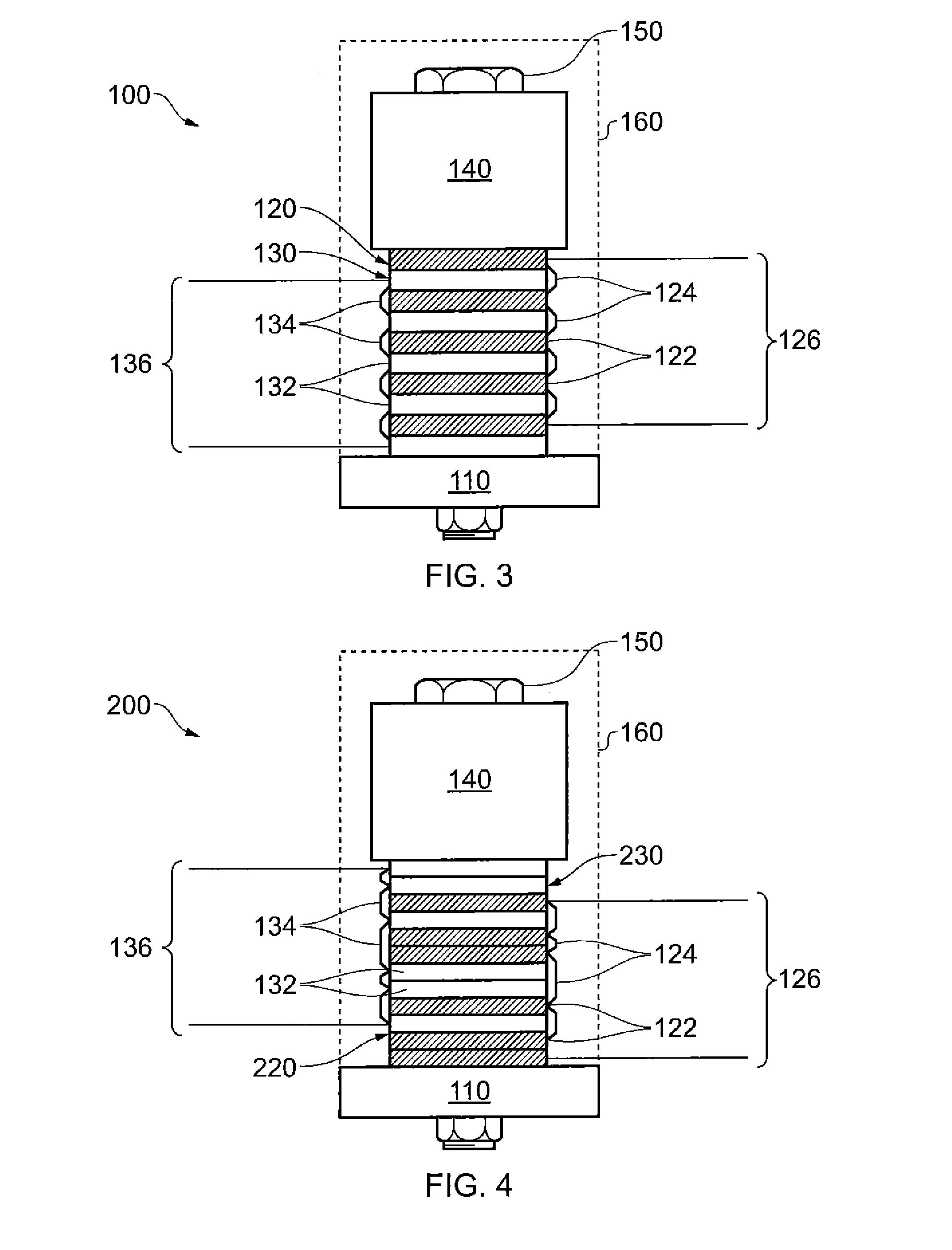
[0057]Referring to FIG. 3, a dual channel accelerometer according to the invention is designated generally by the reference numeral100.
[0058]The dual channel accelerometer 100 comprises a supporting base 110, a first transducer 120, a second transducer 130 and a seismic mass 140. The first transducer 120, second transducer 130 and seismic mass 140 are co-located on the supporting base 110.
[0059]The supporting base 110 is fabricated from steel sheet, although any material having the requisite strength and stiffness properties might alternatively be used.
[0060]The seismic mass 140 is formed from steel with its mass and geometry being selected in accordance with the level of vibration which the dual channel accelerometer 100 is intended to be measuring as well as the sensitivity of the individual piezo-electric sensing elements. These selection criteria are well known in the art and are not repeated herein.
[0061]The first transducer 120 comprises a plurality of first piezoelectric elem...
second embodiment
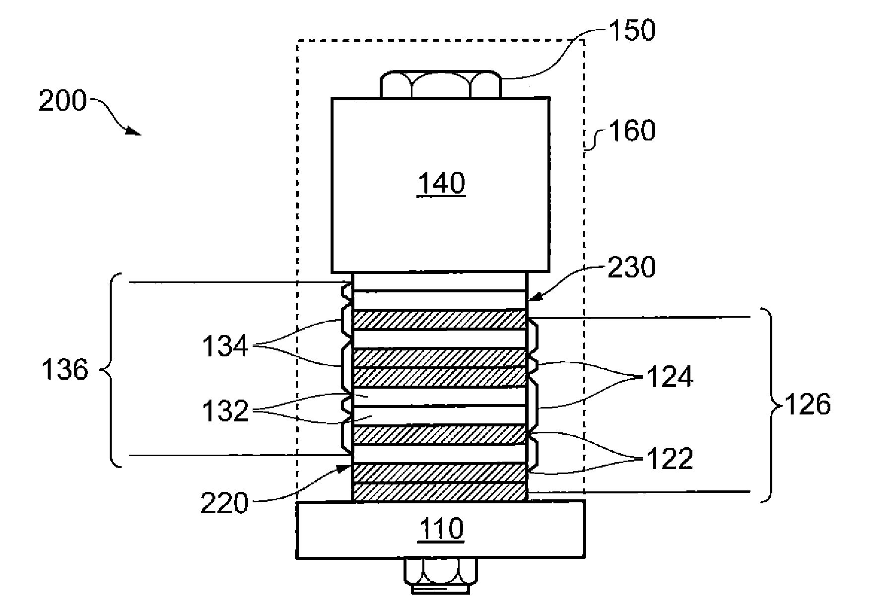
[0068]Referring to FIG. 4, a dual channel accelerometer according to the invention is designated generally by the reference numeral 200. Features of the dual channel accelerometer 200 which correspond to those of apparatus 100 have been given corresponding reference numerals for ease of reference.
[0069]The dual channel accelerometer 200 comprises a supporting base 110, a first transducer 220, a second transducer 230 and a seismic mass 140. In a similar manner to the first embodiment of the invention described above, the first transducer 220, second transducer 230 and seismic mass 140 are co-located on the supporting base 110.
[0070]As for the first embodiment, each of the first and second transducers 220,230 comprises a plurality of respective first and second piezoelectric elements 122,132.
[0071]However, in this embodiment the first and second piezoelectric elements 122,132 are stacked onto the supporting base 110 in a 2-1-1-2 arrangement. In other words, two first piezoelectric ele...
PUM
Property
Measurement
Unit
Mass
aaaaa
aaaaa
Piezoelectricity
aaaaa
aaaaa
Abstract
A dual output accelerometer having first and second output channels, comprises a supporting base, a first transducer comprising a plurality of inter-connected first piezoelectric elements, a second transducer comprising a plurality of inter-connected second piezoelectric elements and a seismic mass.Each of the first piezoelectric elements and the second piezoelectric elements are interleaved with one another, and are co-located with the seismic mass, the co-located first and second piezoelectric elements and the seismic mass being fastened to the supporting base by a rigid mechanical coupling. The interleaved first and second piezoelectric elements provide an improved first output channel to second output channel matching.
Description
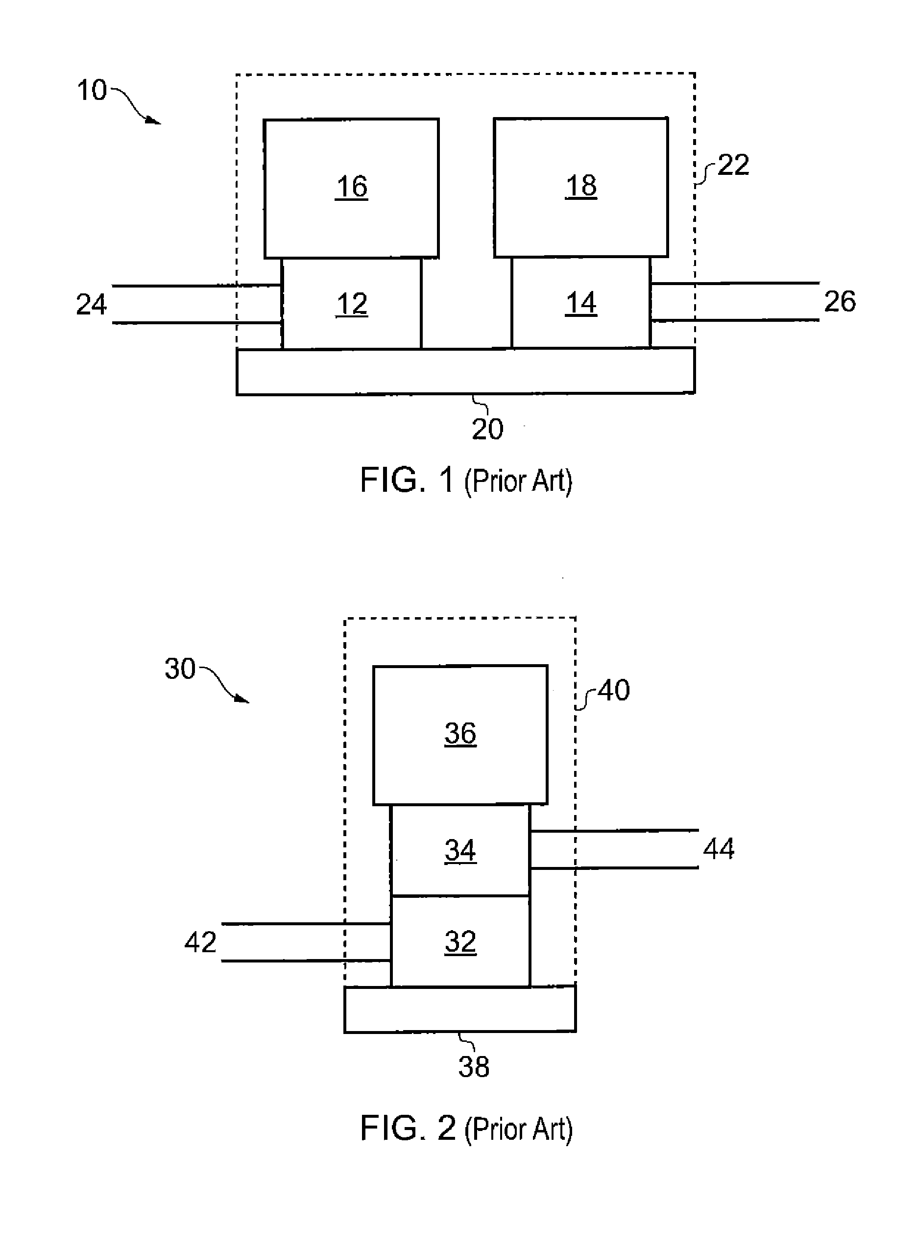
[0001]This invention claims the benefit of UK Patent Application No. 1306757.4, filed on 15 Apr. 2013, which is hereby incorporated herein in its entirety.FIELD OF THE INVENTION[0002]The present invention relates to accelerometers and particularly, but not exclusively, to dual channel accelerometers together with methods of manufacturing the same.BACKGROUND TO THE INVENTION[0003]Accelerometers are used for measuring levels of vibration in many different types of machinery. In many applications, such as for example aircraft engines, there is a need for duplicate measurements of vibration level in order to provide a level of redundancy in case of sensor failure.[0004]It is therefore known to use dual channel accelerometers in such redundant applications. Various arrangements of dual channel accelerometer are known.[0005]One such arrangement, shown in FIG. 1, employs two single channel accelerometers mounted side by side within a common housing. This has the advantage of being simple a...
Claims
Application Information
Patent Timeline
Application Date:The date an application was filed.
Publication Date:The date a patent or application was officially published.
First Publication Date:The earliest publication date of a patent with the same application number.
Issue Date:Publication date of the patent grant document.
PCT Entry Date:The Entry date of PCT National Phase.
Estimated Expiry Date:The statutory expiry date of a patent right according to the Patent Law, and it is the longest term of protection that the patent right can achieve without the termination of the patent right due to other reasons(Term extension factor has been taken into account ).
Invalid Date:Actual expiry date is based on effective date or publication date of legal transaction data of invalid patent.

