
Device for monitoring an air supply flow or a volumetric air flow

A technology of air volume and air delivery, applied in measurement devices, control inputs involving air characteristics, space heating and ventilation control inputs, etc., can solve problems such as increased wear and failure of monitoring devices, and achieve simple and cheap manufacturing. Effect

Inactive Publication Date: 2010-05-12
STEGO HLDG
View PDF4 Cites 0 Cited by
  • Summary
  • Abstract
  • Description
  • Claims
  • Application Information

AI Technical Summary

Problems solved by technology

But this additional structural component makes the monitoring device more prone to failure, for example due to increased wear
In particular it is difficult to design the springs accordingly to ensure air flow monitoring at different flow velocities and / or throughflow rates

Method used


Image

  • Device for monitoring an air supply flow or a volumetric air flow
  • Device for monitoring an air supply flow or a volumetric air flow
  • Device for monitoring an air supply flow or a volumetric air flow

Examples


Embodiment Construction

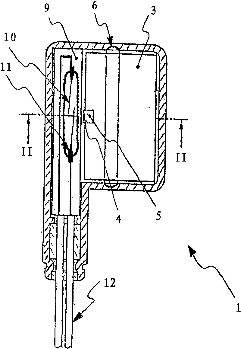
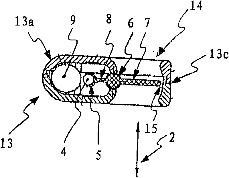
[0029] figure 1 A particular exemplary embodiment is shown in longitudinal section through a device 1 according to the invention for monitoring the air delivery rate or air volume flow 2 . In this case, an upstream device is formed as a rotatably mounted shutter 3 , on which a permanent magnet 4 is mounted in a magnet carrier 5 . The flap 3 is suspended in a swivel bearing 6 and is thus deflected by the air flow 2 through a rotational movement. The permanent magnet 4 is located on the edge of the shutter 3 on an axis of symmetry perpendicular to the axis of rotation.

[0030] Since said shutter 3 is at least provided with a magnet arrangement, here part of a permanent magnet 4 , this shutter 3 is therefore provided with at least one counterweight or similar mass-balancing part, so that it can be mounted independently of gravity and position. In the figure shown, the shutter 3 is arranged eccentrically in order to provide a mass balance by means of different surface dimension...


PUM


Abstract

The invention relates to a device for monitoring an air supply flow or a volumetric air flow, in particular for ventilators which can also be applied for extremely low flow speeds and / or throughput rates. The aim of the invention is to produce a device cheaply and simply with essentially wear-free components which reacts to changes in the flow speed and / or the throughput rate without a time delay.Said aim is achieved, whereby the device comprises an approach flow device, the position of which may be altered relative to a mounting, against a retaining force F<M >and which may be impinged by the air flow for monitoring to generate a change in the position thereof. Furthermore, magnetic devices for the generation of a magnetic field dependent on the position of the approach flow device, detection means for recording the magnetic field and measuring means for generation of a measured signal dependent on the magnetic field are provided. The magnetic field forms at least a part of the retaining force F<M>.

Description

technical field [0001] The invention relates to a device, in particular a ventilator, for monitoring an air delivery rate or an air volume flow. Background technique [0002] Equipment including electrical and / or electronic instruments, such as switchgear, usually must be air-conditioned or effectively ventilated. This form of forced ventilation is used to circulate the air in the switchgear and to ventilate the equipment in a targeted manner, since heat radiation from the installed equipment and also heat exchange with the environment can create a functionally detrimental climate inside the cabinet. In order to ensure continuous ventilation, an additional control unit is required in addition to the own ventilation system, which monitors the operating state of the ventilation with the aid of the air delivery rate or the air volume flow. [0003] Devices for monitoring the air delivery rate or air volume flow are currently often provided in a purely electrical fashion. They...

Claims


Application Information

Patent Timeline
Patent Type & Authority Patents(China)
IPC IPC(8): F24F11/00G01P13/00H01H35/40
CPCG01P13/0026H01H35/405F24F11/001F24F2011/0038F24F11/30F24F2110/00F24F2110/30F24F11/00G01P13/00H01H35/40
Inventor H·艾森豪尔
Owner STEGO HLDG
Learn More