Cam mechanism to raise steering wheel of patient transfer device
What is Al technical title?
Al technical title is built by PatSnap Al team. It summarizes the technical point description of the patent document.
a technology for steering wheel and patient transfer, which is applied in the direction of hand carts with one axis, nursing beds, transportation and packaging, etc., can solve the problems of exacerbated problems, unable to use devices in all settings, and the design of rotating belts cannot be used
Active Publication Date: 2014-10-16
MEDIGLIDER
View PDF0 Cites 16 Cited by
Summary
Abstract
Description
Claims
Application Information
AI Technical Summary
This helps you quickly interpret patents by identifying the three key elements:
Problems solved by technology
Method used
Benefits of technology
[0012]The present invention is generally directed to an improved steerage for a patient transfer device having at least one steering wheel which may be raised for stowage. A camming feature may advantageously be used to raise the wheel. In the illustrative embodiment, the camming feature includes a first bracket which rotates ...
Problems solved by technology
There can still be problems, however, in getting a patient from a bed or other support surface onto a stretcher or gurney.
This problem is exacerbated when the patient is unusually heavy.
This approach can still be difficult if the patient is uncooperative (i.e., unconscious), and can further be very uncomfortable even if the patient is cooperative, due to the frictional engagement of the tray with the body or the lack of firm support by the sheet.
There are still several serious problems with the counter-rotating belt designs.
Because of this limitation, such devices cannot be used in all settings, i.e., wherein there is insufficient clearance space under the bed or table (a situation becoming more common as more accouterments are added to beds and tables that occupy the space underneath).
These devices further only allow loading and unloading along one side of the device, which can present problems when the patient is not suitably oriented (head-to-feet) on the device with respect to the bed or table.
Designs such as ...
Method used
Image
Click on the blue label to locate the original text in one second.
Reading with bidirectional positioning of images and text.
Examples
Embodiment Construction
)
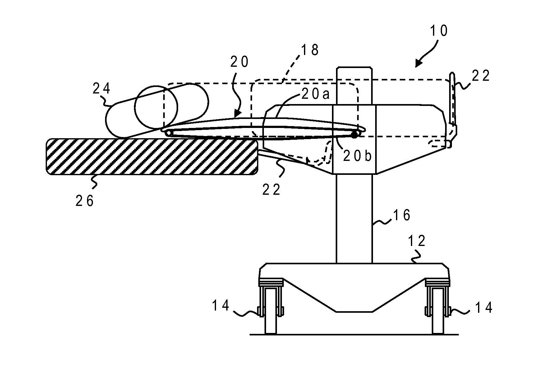
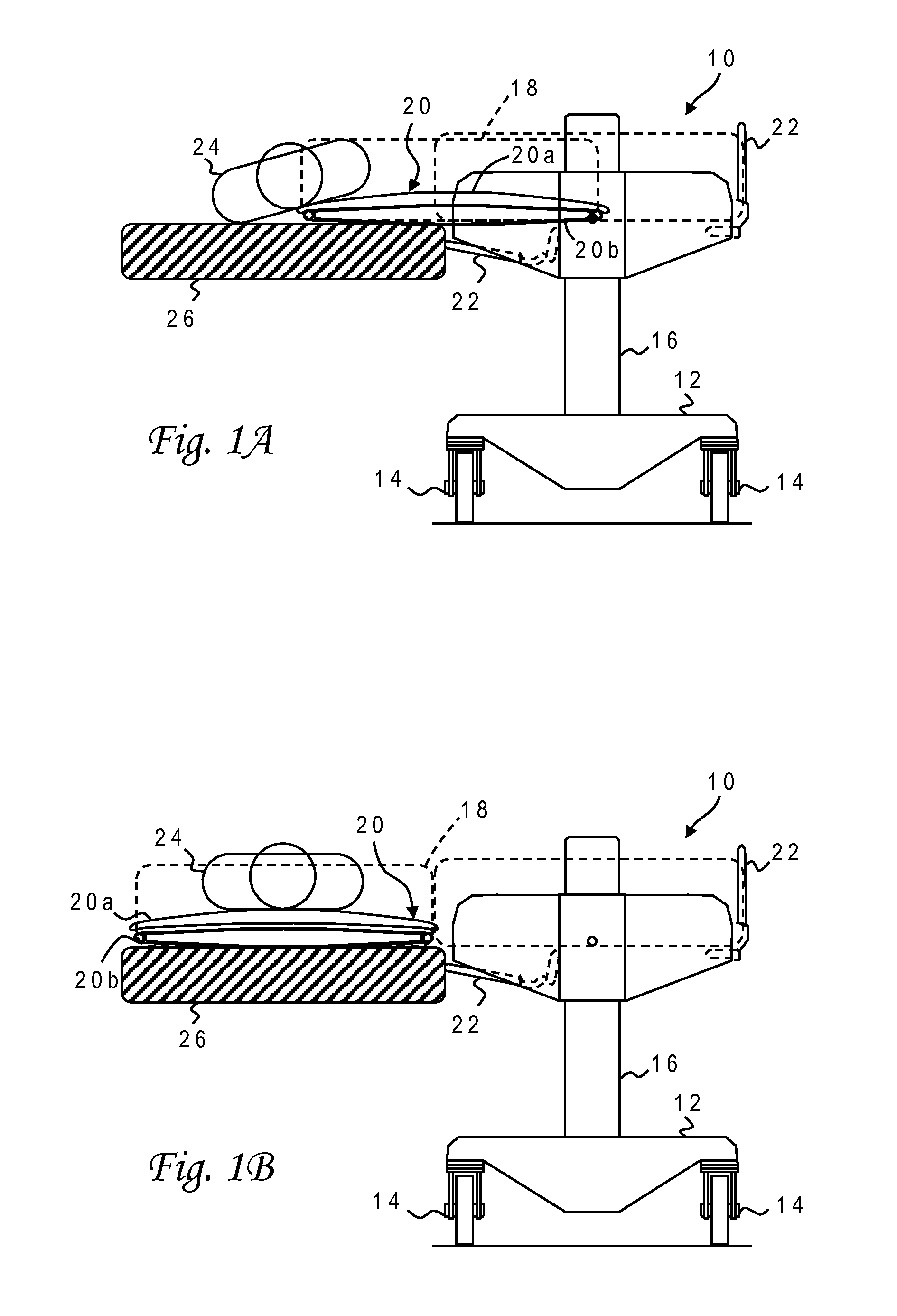
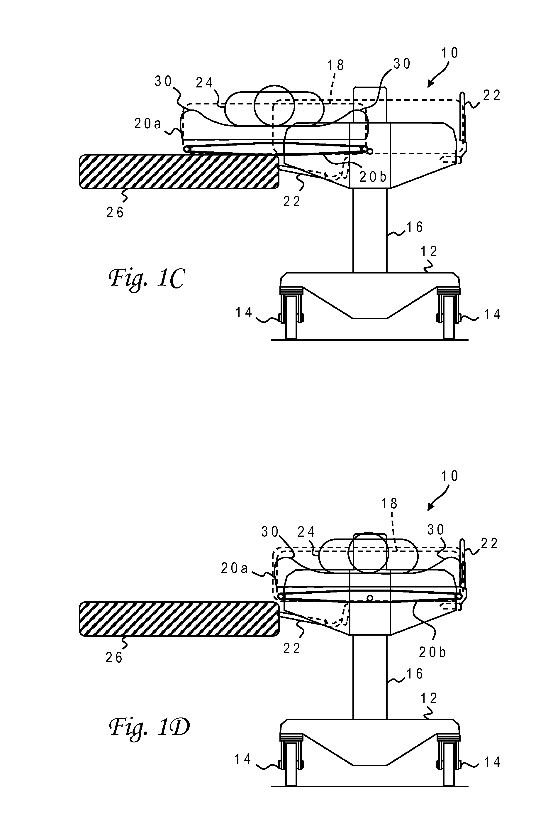
[0029]With reference now to the figures, and in particular with reference to FIGS. 1A-1D, there is depicted one embodiment 10 of a patient transfer device constructed in accordance with the present invention. Patient transfer device 10 is generally comprised of a frame or base 12 mounted on four or more wheels or casters 14, two vertical support members or columns 16 mounted on base 12 which contain powered elevating and lowering means for horizontal slide assemblies 18 attached to support columns 16 and to a belt table sub-frame (not shown) that maintains spacing and vertical alignment of the horizontal slide assemblies and also provides synchronized drive power to each slide assembly so they stay in alignment during the extension and retraction process, a table assembly 20 attached to slide assemblies 18, and side rails 22 attached to the belt table sub-frame.
[0030]FIG. 1A illustrates a patient acquisition position of slide assembly 18 and table assembly 20 wherein a leading edge...
PUM
Abstract
A table assembly for a patient transfer device has an upper table with side plates that are differentially extended at the ends, and valve control for pneumatic tubing integrated with retraction of the side plates. During patient delivery only the delivery side plate is raised, to avoid catching linens in the nip formed between upper and lower belts. A slide assembly supporting the table assembly includes a fixed plate, an intermediate plate, and a full-motion plate which extend by means of rack-and-pinion drives. Each plate is symmetrical, and pinions are symmetrically located on opposite sides of the fixed or intermediate plate to allow hyperextension to either the left or right. Improved steerage for the device is provided by two centerline wheels which counter-rotate from a straight position to a turning position and further to a lateral position wherein the wheels are orthogonal to the longitudinal centerline of the device.
Description
CROSS-REFERENCE TO RELATED APPLICATION[0001]This application is a divisional of U.S. patent application Ser. No. 13 / 492,807 filed Jun. 9, 2012, which is a continuation of U.S. patent application Ser. No. 12 / 188,847 filed Aug. 8, 2008, now U.S. Pat. No. 8,214,943, which is a continuation-in-part of U.S. patent application Ser. No. 11 / 837,671 filed Aug. 13, 2007, now U.S. Pat. No. 7,861,336, which is a continuation-in-part of U.S. patent application Ser. No. 11 / 534,535 filed Sep. 22, 2006, now U.S. Pat. No. 7,540,044, which is a continuation-in-part of U.S. patent application Ser. No. 11 / 246,426 filed Oct. 7, 2005, now U.S. Pat. No. 7,603,729, each of which is hereby incorporated.BACKGROUND OF THE INVENTION[0002]1. Field of the Invention[0003]The present invention generally relates to devices for moving objects, and more particularly to a tray or table assembly for a patient transfer device wherein the table assembly includes upper and lower tables having counter-rotating, endless bel...
Claims
Application Information
Patent Timeline
Application Date:The date an application was filed.
Publication Date:The date a patent or application was officially published.
First Publication Date:The earliest publication date of a patent with the same application number.
Issue Date:Publication date of the patent grant document.
PCT Entry Date:The Entry date of PCT National Phase.
Estimated Expiry Date:The statutory expiry date of a patent right according to the Patent Law, and it is the longest term of protection that the patent right can achieve without the termination of the patent right due to other reasons(Term extension factor has been taken into account ).
Invalid Date:Actual expiry date is based on effective date or publication date of legal transaction data of invalid patent.