
System and method for mathematical predictive analytics and computational energy modeling

a computational energy modeling and predictive analytics technology, applied in the field of managing electrical grids, can solve the problems of preventing the availability of renewable power sources such as solar power and wind, preventing the availability of sustained, reliable energy sources for power generation, etc., to achieve the effect of maximizing electricity production, reducing pollution, cost, and service interruptions, and minimizing pollution and costs

Active Publication Date: 2014-10-16
LOCKHEED MARTIN CORP
View PDF0 Cites 17 Cited by
  • Summary
  • Abstract
  • Description
  • Claims
  • Application Information

AI Technical Summary

Benefits of technology

The patent describes a system, method, and computer software for controlling a small electrical power grid. The system allows the grid to assess the availability of energy sources, estimate demand, and choose the best way to produce electricity to meet those demands while minimizing costs, pollution, and service interruptions. The main technical effect is an efficient and effective way to manage micro grids to maximize production while minimizing waste and cost.

Problems solved by technology

However, some of these power sources may not provide a sustained, reliable energy source for power generation.
For instance, renewable power sources, such as solar power and wind, may be susceptible to environmental factors that might hinder their availability when electricity is badly needed.
Hence, these power sources are often called intermittent because there might be periods of gaps in their availability.
On the other hand, more stable energy sources, such as coal, oil, or natural gas, often produce undesired pollutants as a by-product of their operation.
This has resulted in environmental regulations that limit these emissions and hence restrict their use.

Method used


Image

  • System and method for mathematical predictive analytics and computational energy modeling
  • System and method for mathematical predictive analytics and computational energy modeling
  • System and method for mathematical predictive analytics and computational energy modeling

Examples


Embodiment Construction

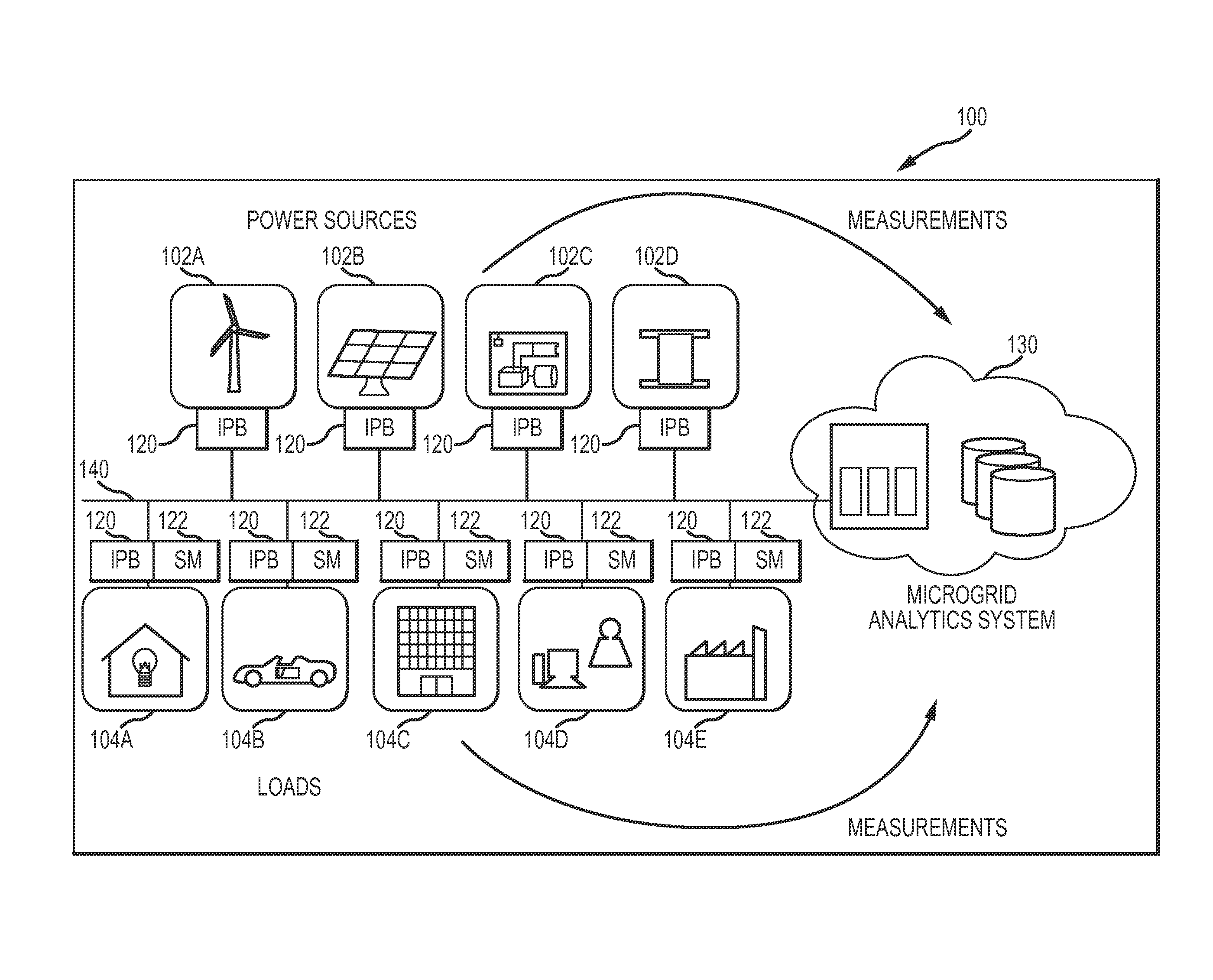
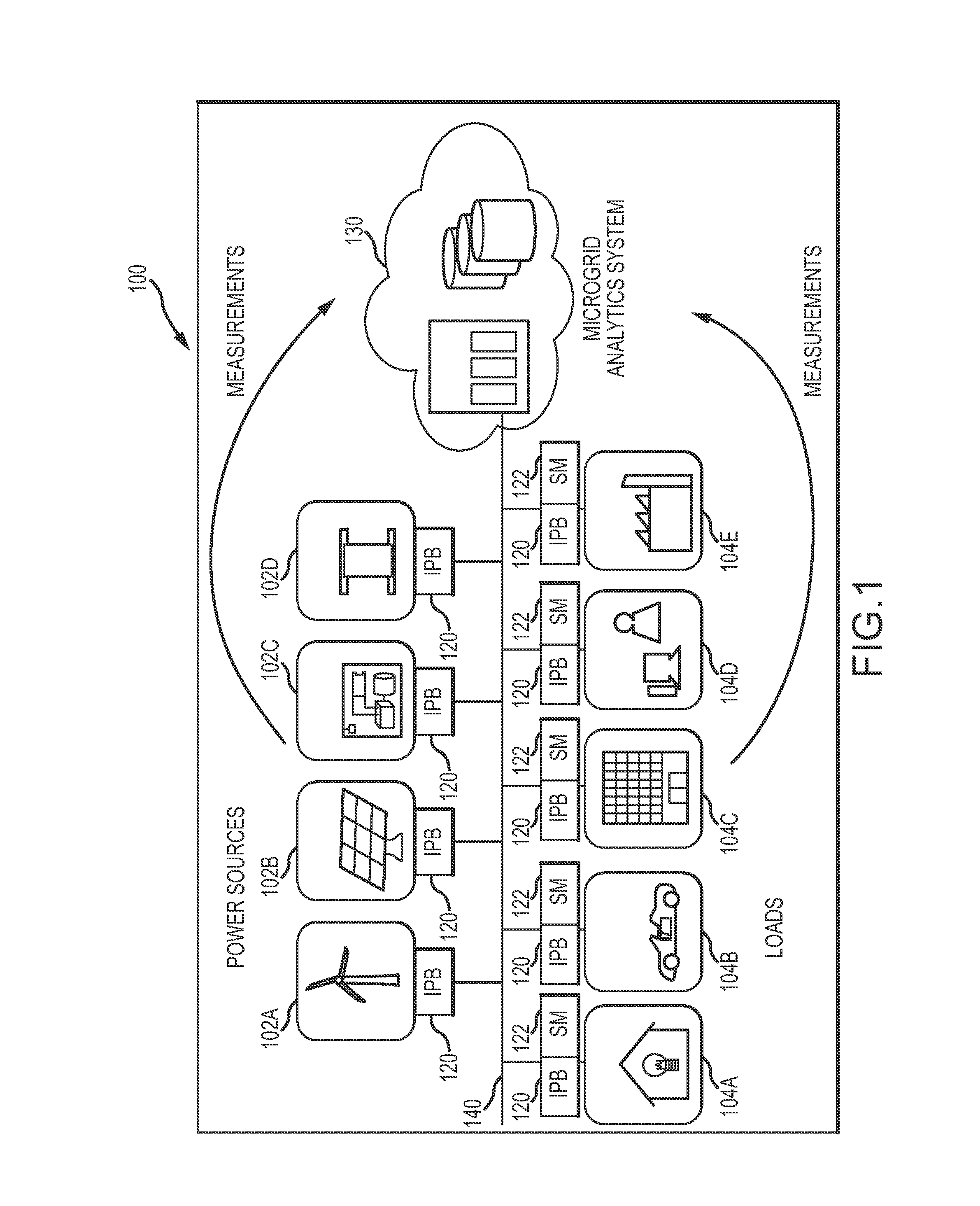
[0017]FIG. 1 shows one embodiment of a managed micro electrical power grid 100 system architecture. The micro electrical power grid 100 may include a one or more electrical power sources 102A-102D and one or more electrical loads 104A-104E. As may be typical in a Micro Grid environment, the micro electrical power grid 100 may be configured without transmission lines bringing electricity from distant sources and may instead rely on localized distributed electricity generation. In this regard, the electrical power sources 102A-102D may, for example, include renewable sources such as wind 102A and solar 102B, diesel / natural gas generators 102C, and battery banks 102D. Other electrical power sources that are not illustrated such as, for example, geothermal, fuel cells, and micro-turbines may also be included in the micro electrical power grid 100 architecture. The electrical loads 104A-104F may, for example, include homes 104A, vehicles 104B, office buildings 104C, data centers 104D, fa...


PUM


Abstract

Systems, methods and computer program products for controlling a micro electrical power grid to select the volume of electricity produced by each power generation source in order to meet demand and achieve a particular optimization goal. In one embodiment, a system operable to control a micro electrical power grid may include a plurality of intelligent power broker (IPB) units and at least one data analytics unit in communication with the IPB units. Each IPB may be associated with an electrical power source or an electrical load and may be operable to collect data relating to its associated electrical power source or electrical load. The data analytics unit may receive the data from the IPB units and may be operable to analyze the data and direct the IPBs to remove one or more of the electrical power loads from the micro electrical grid and / or increase an electrical power output from the electrical sources during time period T.

Description

RELATED APPLICATION INFORMATION[0001]This application claims priority from U.S. Provisional Application Ser. No. 61 / 812,110, entitled “ADVANCED SENSOR FOR ENERGY BROKERAGE” filed on Apr. 15, 2013, which is incorporated by reference herein in its entirety.FIELD OF THE INVENTION[0002]The present invention relates generally to managing electrical grids, and more particularly to managing smart electrical grids having distributed localized electrical generation.BACKGROUND OF THE INVENTION[0003]Modern electric power grids may combine a diverse array of power generation units fueled by coal, nuclear energy, natural gas, solar power, wind, oil, biodiesel, and / or hydro power, just to name a few. However, some of these power sources may not provide a sustained, reliable energy source for power generation. For instance, renewable power sources, such as solar power and wind, may be susceptible to environmental factors that might hinder their availability when electricity is badly needed. Hence,...

Claims


Application Information

Patent Timeline
IPC IPC(8): H02J4/00
CPCH02J4/00H02J3/008H02J3/06H02J3/381H02J2300/10H02J2300/40H02J2310/10H02J2310/16Y02B70/3225Y04S20/222Y04S50/10
Inventor GREER, MELVINRODRIGUEZ-MARTINEZ, MANUEL
Owner LOCKHEED MARTIN CORP
Learn More