Method and Apparatus for Detection and Quantification of Borehole Standoff

a technology for detecting and quantifying the position of the borehole, which is applied in the direction of reradiation of the borehole/well, instruments, etc., can solve the problems of affecting the extraction of formation fluids,

Active Publication Date: 2014-10-16
WEATHERFORD TECH HLDG LLC
View PDF4 Cites 7 Cited by
  • Summary
  • Abstract
  • Description
  • Claims
  • Application Information

AI Technical Summary

Problems solved by technology

If excessive mudcake deposition occurs, issues such as stuck pipe and damage to the formation may occur.
In addition, if mudcake thickness is inappropriately excessive, it may be more difficult for formation fluids, such as oil and gas, to be extracted from the formation.
Currently, several tools are sensitive to the presence and thickness of mudcake.
The influence of mudcake, especially in the case of resistive formation and a conductive and thick mudcake, is a major disadvantage for the purpose of determining Rxo.

Method used


Image

  • Method and Apparatus for Detection and Quantification of Borehole Standoff
  • Method and Apparatus for Detection and Quantification of Borehole Standoff
  • Method and Apparatus for Detection and Quantification of Borehole Standoff

Examples


Embodiment Construction

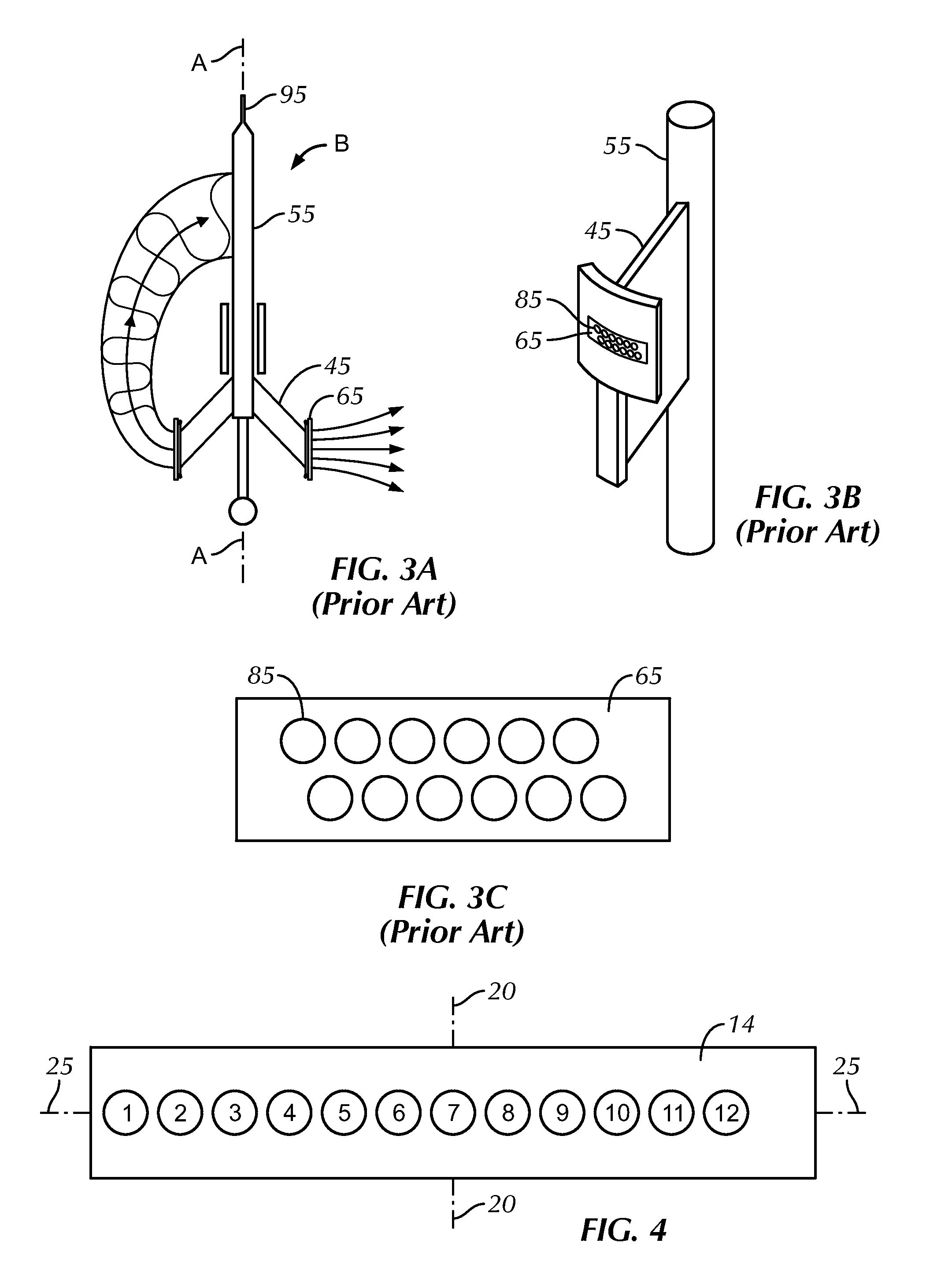
[0039]FIG. 4 illustrates a pad 14 according to the present disclosure. Pad 14 could be disposed on any of the electrical imaging tools discussed above. As discussed above, when operating an electrical image logging tool, current is emitted from button electrodes (i.e. buttons) B1, B2, B3, B4, B5, B6, B7, B8, B9, B10, B11 and B12. Pad 14 and buttons B1-B12 are held at the same potential (voltage). Thus, the pad 14 is an equipotential surface.

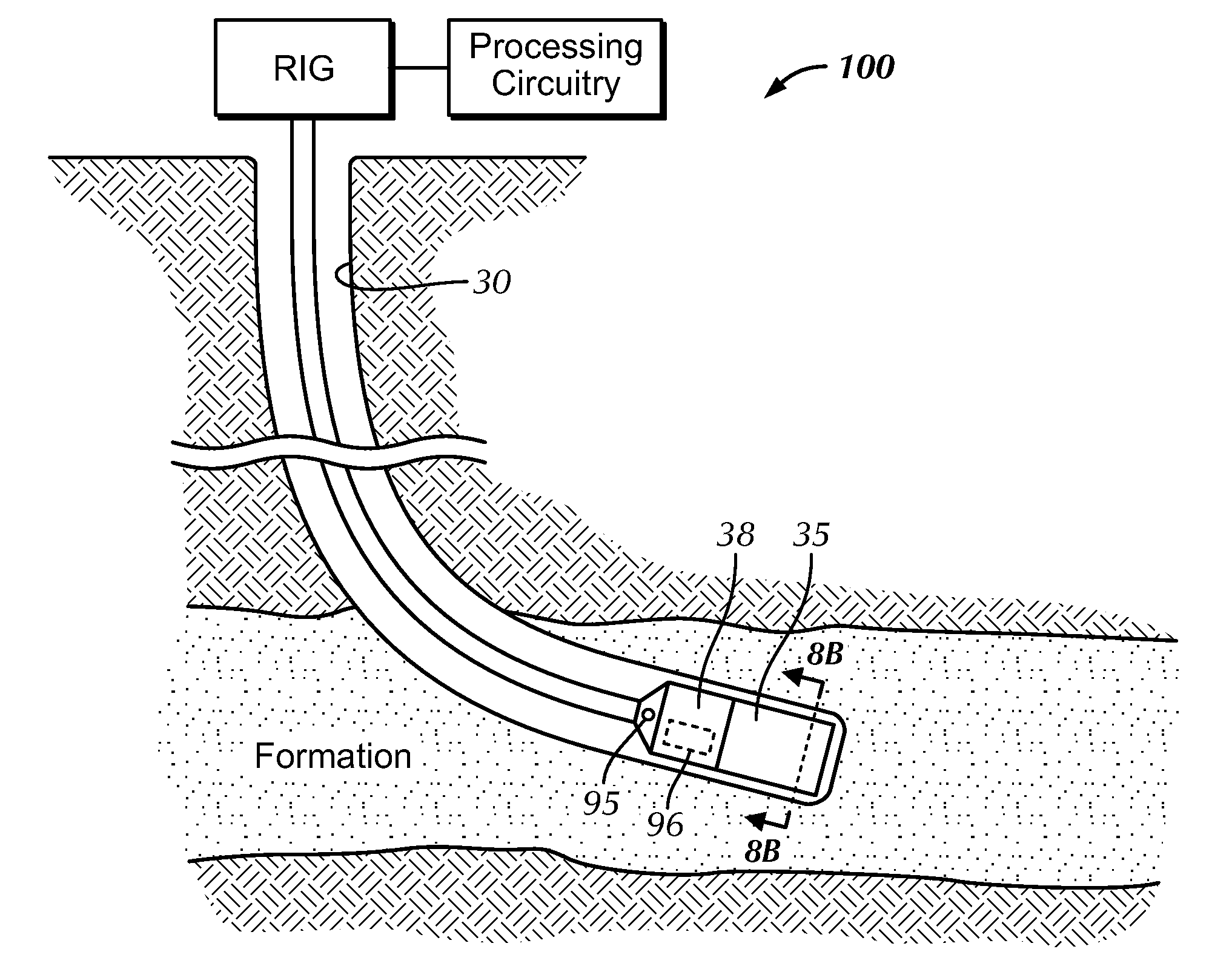
[0040]During use, the emitted current returns to a current-return electrode on the tool string. For example, as seen in FIG. 3A, the current-current return electrode 95 may be located on a mandrel 55 located above / uphole from the pads 14 located on the arms of tool B. As shown in FIG. 4, the buttons B1-B12 are arranged along a line 25. When disposed on the tool, the line 25 of buttons B1-B12 are preferably arranged to be perpendicular to the axis A of the tool in a manner similar to the configuration on the pad of the tool in FIG. 3B. It should b...


PUM


Abstract

A method of quantifying borehole properties, comprising: injecting an electric current from an outer button and an inner button disposed on an equipotential pad into a subterranean formation surround by the borehole, measuring an apparent conductivity or a scaled current for each button, modeling the measurements at a sequence of standoff locations, and, using an inversion technique to determine at least one of the following borehole properties: mudcake thickness, mudcake resistivity, diameter of invasion, flushed zone resistivity and true formation resistivity.

Description

CROSS-REFERENCE TO RELATED APPLICATIONS[0001]Not Applicable.[0002]BACKGROUND OF THE DISCLOSURE[0003]Drilling fluid, also known as “drilling mud” or “mud,” has been employed in drilling for a many years. Drilling fluids may be water based, oil based or synthetic based. Any of a number of liquid and gaseous fluids and mixtures of fluids and solids (as solid suspensions, mixtures and emulsions of liquids, gases and solids) used in operations to drill boreholes into the earth may be used as drilling fluids. In addition, drilling fluids may contain emulsified water, oil, suspended solids or a combination of these materials. In short, drilling fluids may be any substance that will limit or prevent formation fluids from entering a wellbore.[0004]Among the positive benefits of drilling mud is better control of the wellbore. Specifically, if the drilling fluid is of an appropriate weight it can, at least in part, assist in controlling unwanted inflow into the wellbore from the surrounding fo...

Claims


Application Information

Patent Timeline
Patent Type & Authority Applications(United States)
IPC IPC(8): G01V3/20
CPCG01V3/20E21B49/00
Inventor HU, DAVID GUOYU
Owner WEATHERFORD TECH HLDG LLC
Why Eureka
Try Eureka