
Apparatuses and methods for iris imaging

a technology of iris imaging and apparatus, applied in the field of iris imaging apparatus, can solve the problems of increasing the cost of manufacturing of imaging apparatus, increasing the cost of imaging apparatus, and significantly increasing the cost of manufacturing of either solution

Inactive Publication Date: 2014-10-16
DELTA ID
View PDF6 Cites 26 Cited by
  • Summary
  • Abstract
  • Description
  • Claims
  • Application Information

AI Technical Summary

Benefits of technology

The patent describes a method for capturing images of an iris by using a light source to make the pupil constrict. This helps to optimize the area of the iris that can be captured. The technical effect is improved image quality and efficiency in eye biometric analysis.

Problems solved by technology

A consequence of existing solutions for providing illumination in the near infrared region, is the high cost of infrared LEDs—which can cause costs of manufacture of imaging apparatuses to increase.
The increase in cost is yet more significant for imaging apparatuses seeking to provide an illumination spread covering a range (or multiple ranges) of wavelengths within the near infrared region (e.g. across the entire 700 nm to 900 nm region).
It would be understood that the costs of incorporating either of these solutions significantly adds to the cost of manufacture.
A second set of problems commonly associated with iris recognition systems are those arising in connection with ambient light i.e. light from a source other than the intended source of iris illumination.
Ambient light can interfere with iris recognition systems in several ways.
Ambient light also gives rise to specular reflections which are captured by the imaging apparatus, and which interfere with pattern recognition.
Yet further, ambient light can cause difficulties for image capture despite introduction of filters for attenuating visible wavelengths.
Since, such filters transmit infrared radiation, they allow passage of the infrared component of ambient light to, which infrared component thereafter interferes with image formation by infrared waves from the illumination source.
Increasing intensity of infrared radiation incident on a subject's iris can however cause discomfort and may also damage the iris.
It would however be understood that all of the above solutions for addressing problems caused by ambient light, such as use of filters, strobed illumination and shuttered cameras increase the complexity, size and cost of the imaging apparatus.
Additionally, even with the use of filters, prior art devices often require to increase intensity of infrared radiation generated at the illumination source, which can be harmful for the subject.

Method used


Image

  • Apparatuses and methods for iris imaging
  • Apparatuses and methods for iris imaging
  • Apparatuses and methods for iris imaging

Examples


Embodiment Construction

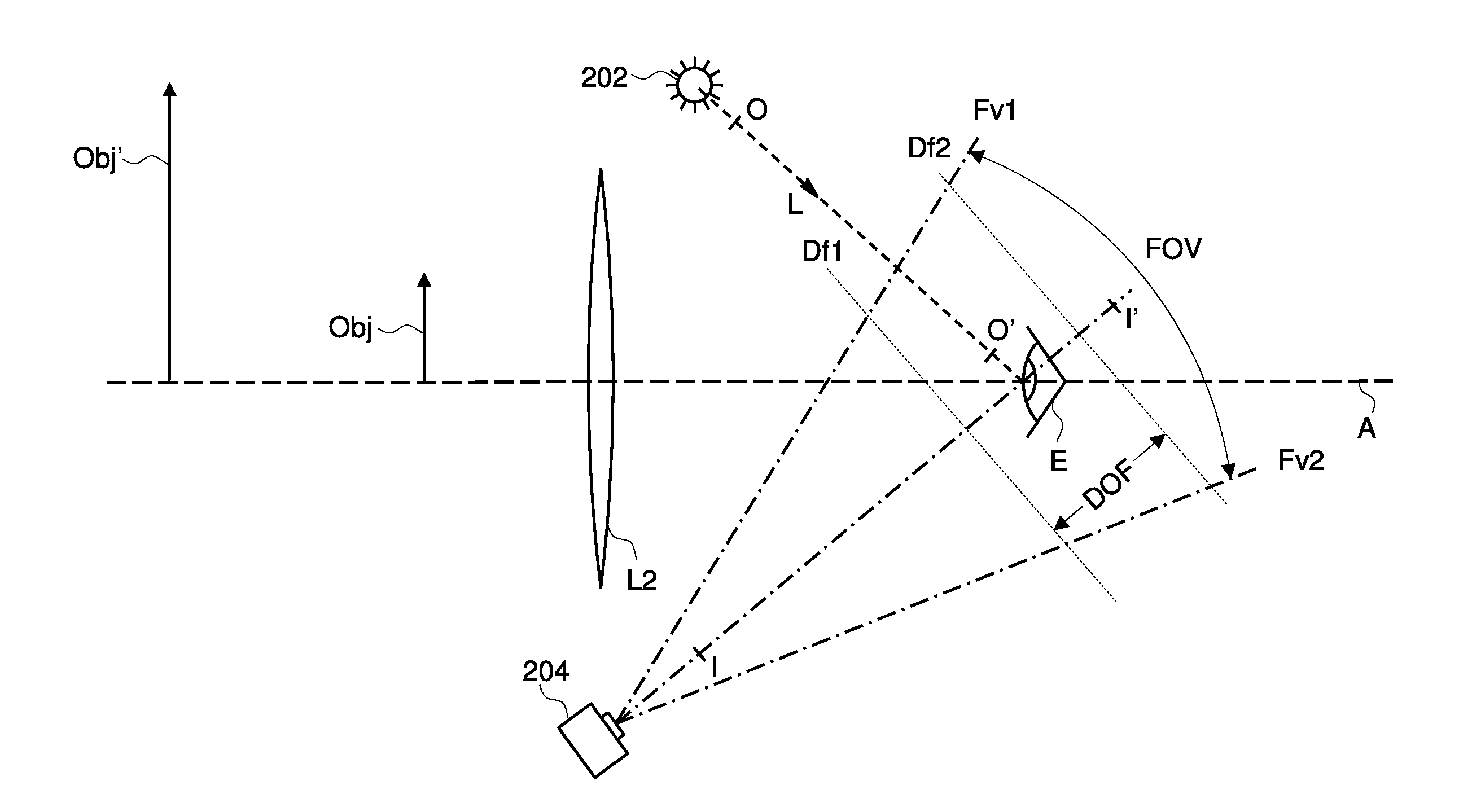
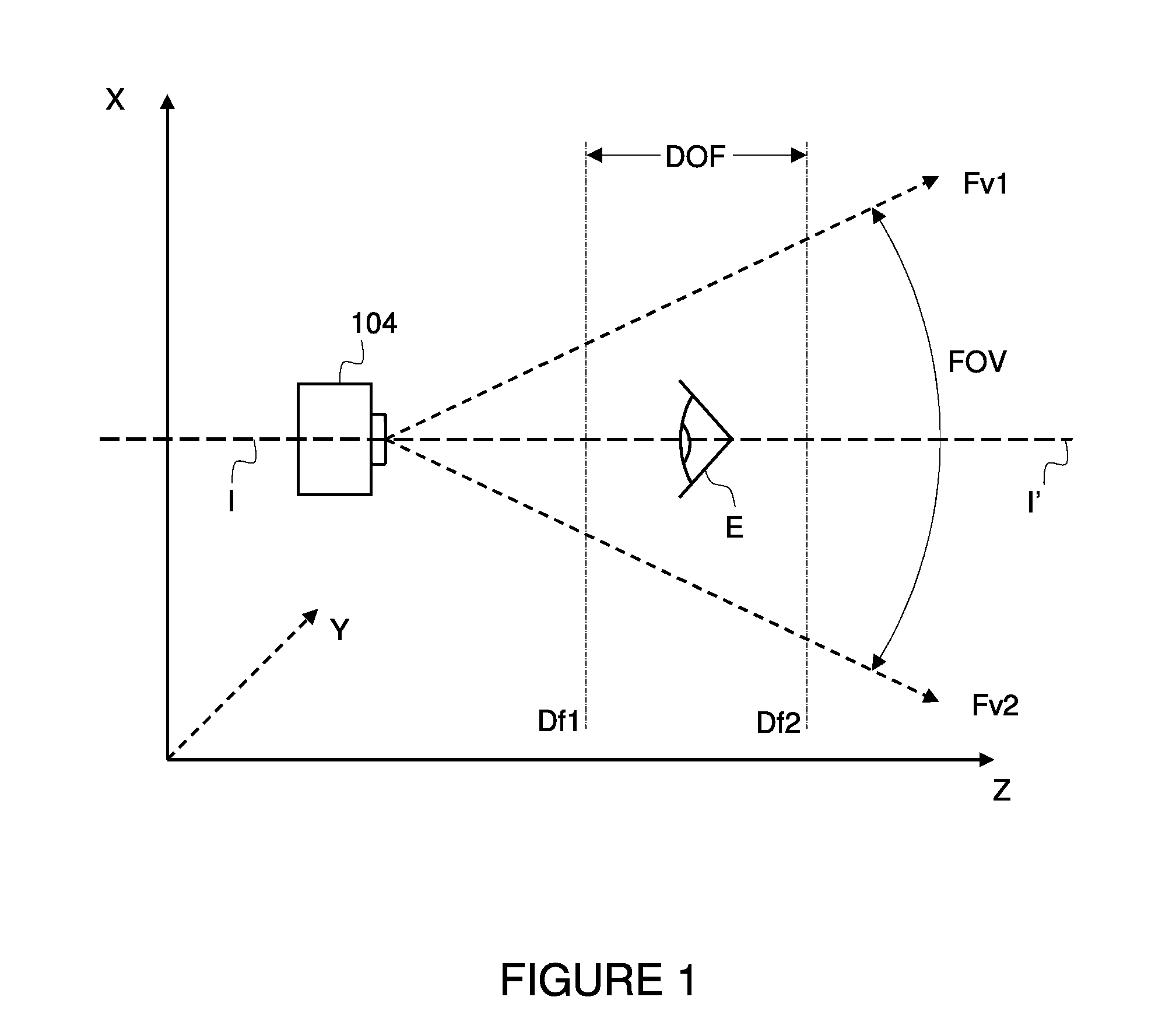
[0052]FIG. 1 illustrates some considerations for correct positioning of the subject's eye for image capture. As illustrated in FIG. 1, iris imaging camera 104 has a finite and fixed field of view FOV (i.e. the volume of inspection capable of being captured on the camera's image sensor). In FIG. 1, field of view FOV is the region defined by dashed lines Fv1 and Fv2. Iris imaging camera 104 additionally has a depth of field DOF—wherein depth of field DOF defines the region within which a subject's iris would appear acceptably sharp and in sufficient detail for the purposes of iris image capture. In FIG. 1, depth of field DOF is the region between dashed lines Df1 and Df2, along the z axis.

[0053]For image acquisition, subject's eye E is required to be positioned within the volume defined by the intersection of the field of view FOV and the depth of field DOF—which ensures that the acquired iris image has sufficient sharpness and detail. Portions of subject's eye E that remain outside t...


PUM


Abstract

The invention includes a method and apparatus for acquiring an image of a subject's iris, within the near infrared region of the electromagnetic spectrum. Near infrared radiation is generated from an incandescent light source, having wavelengths spread across 700 nm to 900 nm. The iris is illuminated for imaging by directing the generated near infrared radiation along an optical path between the incandescent light source and an intersection of a field of view region and depth of field region of an iris camera. Near infrared radiation scattered by the iris and transmitted along the iris camera's optical axis is received at the iris camera. An image of the iris is then acquired at the iris camera, based on radiation scattered by the iris and received at the iris camera.

Description

FIELD OF INVENTION[0001]The invention relates to an imaging apparatus, for obtaining images of one or more features of a subject's eye for biometric identification. The invention is particularly operable to obtain images of a subject's iris for iris recognition.BACKGROUND[0002]Methods for biometric identification based on facial features, including features of the eye are known. Methods for iris recognition implement pattern-recognition techniques to compare an acquired image of a subject's iris against a previously stored image of the subject's iris, and thereby determine or verify identity of the subject. A digital template corresponding to an acquired iris image is encoded based on the image, using mathematical / statistical algorithms. The digital template is thereafter compared against databases of previously encoded digital templates (corresponding to previously acquired iris images), for locating a match and thereby determining or verifying identity of the subject.[0003]Apparat...

Claims


Application Information

Patent Timeline
IPC IPC(8): G06K9/00
CPCG06K9/00604G06V40/19
Inventor PRABHAKAR, SALIL
Owner DELTA ID
Learn More