Camera Module and a Method for Assembling the Same

Active Publication Date: 2014-10-16
LG INNOTEK CO LTD
View PDF2 Cites 14 Cited by
  • Summary
  • Abstract
  • Description
  • Claims
  • Application Information

AI Technical Summary

Benefits of technology

[0024]The present invention has an advantageous effect in that a structure and a method are realized capable of forming a first spiral-removed region at a lens barrel, and filling an epoxy between the first spiral -removed region and the lens barrel to perform a focusing process, whereby an erroneous operation during focusing process, and a twisted scope of depth of focus between a lens and an image sensor (i.e., focusing of a lens and an image sensor) caused by product movem

Problems solved by technology

At this time, during epoxy coating process, inattention may occur of touching the lens barrel using a coating needle to generate a problem of twisting a

Method used


Image

  • Camera Module and a Method for Assembling the Same
  • Camera Module and a Method for Assembling the Same
  • Camera Module and a Method for Assembling the Same

Examples


Example

[0031]Now, a camera module and a method for assembling the camera module according to exemplary embodiments of the present invention will be described in detail with reference to the accompanying drawings.

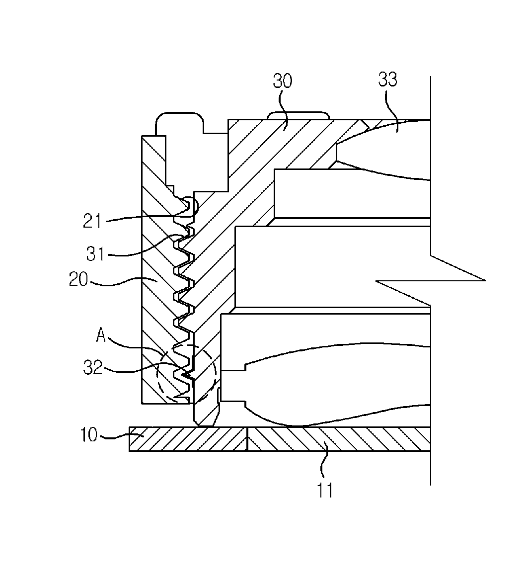
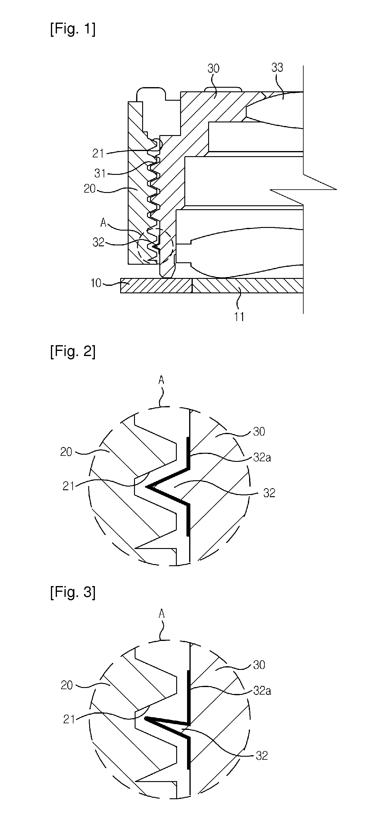
[0032]FIG. 1 is a cross-sectional view illustrating a schematic structure of a camera module according to the present invention, FIGS. 2, 3 and 4 are partial enlarged views of ‘A’ part of FIG. 1 according to mutually different exemplary embodiments of the present invention.

[0033]Referring to FIGS. 1 to 4, a camera module according to the present invention includes a base (10), a bobbin (20) and a lens barrel (30).

[0034]The base (10) is arranged at an upper surface of a PCB (Printed Circuit Board, not shown) and an IRCF (Infrared Cut Filter, 11) is arranged at a position corresponding to a position of an image sensor mounted on the PCB. The bobbin (20) is liftably arranged at an upper surface of the base (10), and the bobbin (20) is protrusively formed at a floor surface with a plur...


PUM

PropertyMeasurementUnit
Thicknessaaaaaaaaaa
Angleaaaaaaaaaa
Distanceaaaaaaaaaa

Abstract

The present invention relates to a camera module, the camera module including a base formed at an upper surface of a PCB (Printed Circuit Board) mounted with an image sensor, and formed with an IRCF (Infrared Cut Filter) at a position corresponding to that of the image sensor, a bobbin vertically reciprocatively formed at an upper surface of the base, and having a bobbin screw thread at an upper surface, a lens barrel formed with a lens barrel screw thread at an outer surface for being screw-connected to an interior of the bobbin and mounted with at least one or more lenses, and a foreign object blocking unit formed at a screw-connected portion between the bobbin and the lens barrel to prevent sticky and adhesive foreign objects from being transmitted to an IRCF (Infrared Cut Filter) in the course of screw-connection between the lens barrel and the bobbin.

Description

TECHNICAL FIELD[0001]The teachings in accordance with exemplary embodiments of this invention relate generally to a camera module and a method for assembling the same.BACKGROUND ART[0002]Generally, a camera module is an optical device formed with a plurality of lenses for photographing an object through the lenses. The lenses are embedded in a lens barrel. The lens barrel is coupled to a holder, and the holder is attached to a substrate mounted with an image sensor. At this time, the lens barrel is moved to perform a focusing process to adjust a depth of focus between the lens embedded in the lens barrel and the image sensor (i.e., focusing of the lens barrel and the image sensor).[0003]Conventionally, after the focusing process, in order to fix the lens barrel and the holder, an epoxy is coated between the lens barrel and the holder to allow the epoxy to cure. At this time, during epoxy coating process, inattention may occur of touching the lens barrel using a coating needle to gen...

Claims


Application Information

Patent Timeline
IPC IPC(8): H04N5/225H04N5/33H05K3/30
CPCH04N5/2257G03B17/12H05K3/30H04N5/33H04N5/2253Y10T29/4913H04N23/57H04N23/55H04N23/54H05K3/284
Inventor YEON, BYOUNG YUNCHAE, KYUNG PILJUNG, CHEOL WOO
Owner LG INNOTEK CO LTD
Why Eureka
Try Eureka