
Auto-Injection Device

a technology of injection device and syringe, which is applied in the field of auto-injection device, can solve the problems of significant risk of fragile syringe damage and significant risk of fragile syringe breakage, and achieve the effects of reducing the risk of syringe damage when a drive force is applied by the drive mechanism, and facilitating the fitting of syring

Active Publication Date: 2014-10-16
SHL MEDICAL AG
View PDF6 Cites 17 Cited by
  • Summary
  • Abstract
  • Description
  • Claims
  • Application Information

AI Technical Summary

Benefits of technology

This patent describes an improved injector device that supports the syringe along its length and reduces the risk of damage to the syringe when a drive force is applied. The C-shaped collar on the syringe holder allows for easy fitting of the syringe and facilitates the distribution of load over a larger area, reducing the risk of damage. The guiding means in the autoinjector device help during preparation, assisting with the mounting of the syringe and holder in the housing. The openings or windows in the housing and syringe holder make it easy to verify the syringe is correctly fitted.

Problems solved by technology

However, syringes are fragile and when the force of the drive mechanism is applied, there is a significant risk that the fragile syringe breaks.
The support device reduces the risk of damage to the syringe but there is till a significant risk that the fragile syringe is damaged when a large force from the drive mechanism is applied upon activation of the autoinjector.

Method used


Image

  • Auto-Injection Device
  • Auto-Injection Device
  • Auto-Injection Device

Examples


Embodiment Construction

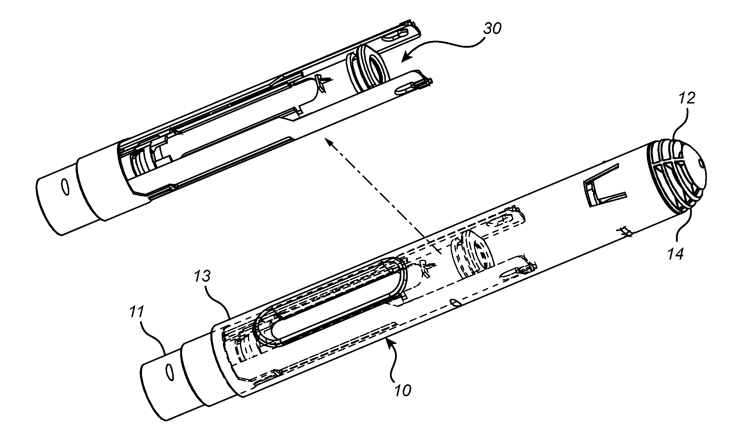
[0032]In FIGS. 3a to 3c, selected components of an autoinjector device 10 according to the invention are illustrated. The autoinjector device 10, elongated along a longitudinal axis A, is intended for self-administration of drugs and has a proximal end 11 and an opposing distal end 12.

[0033]The autoinjector device comprises an autoinjector housing divided into a proximal housing section 13 and distal housing section 14 in order to make the space defined inside the housing accessible for assembly of the different components of the autoinjector.

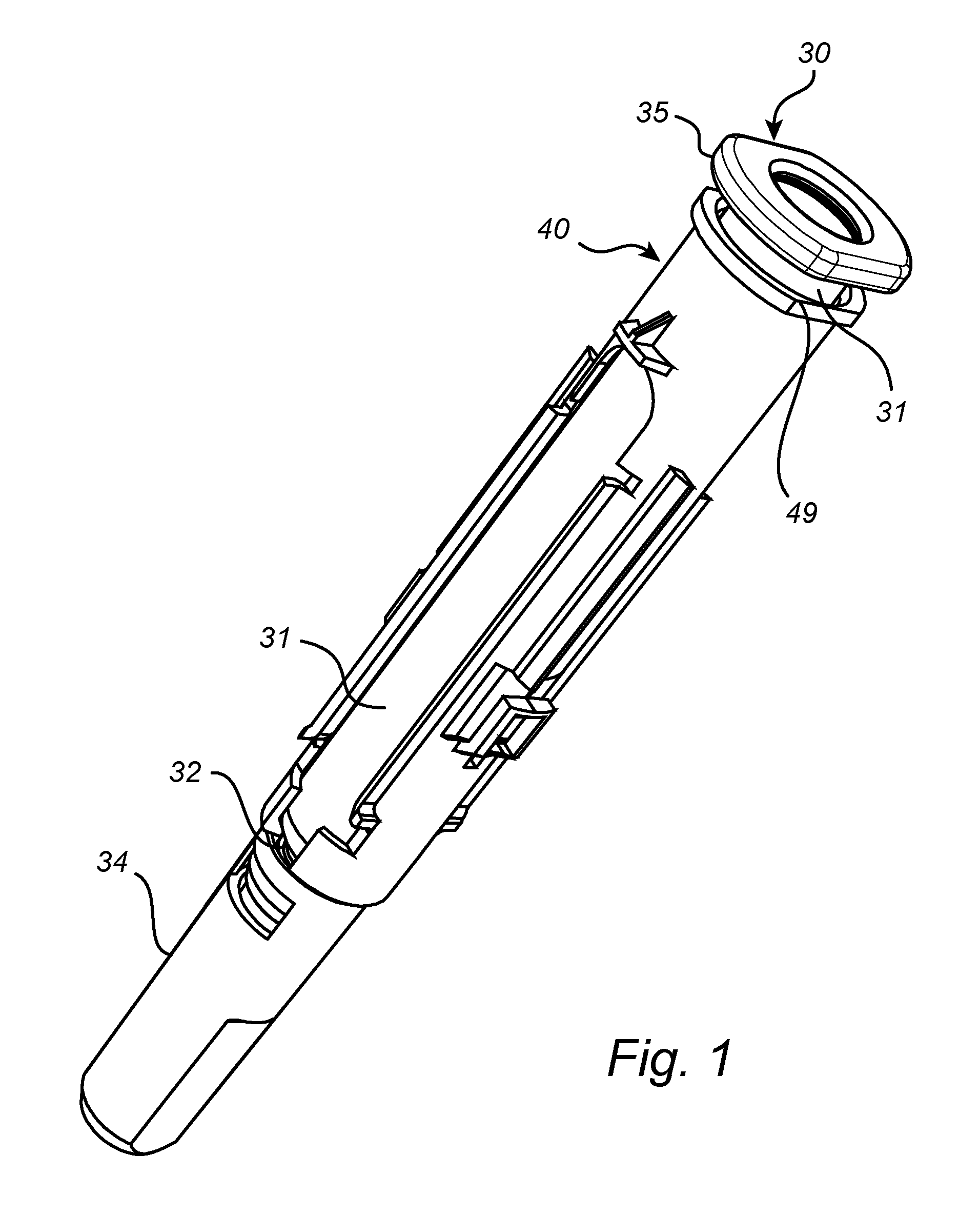
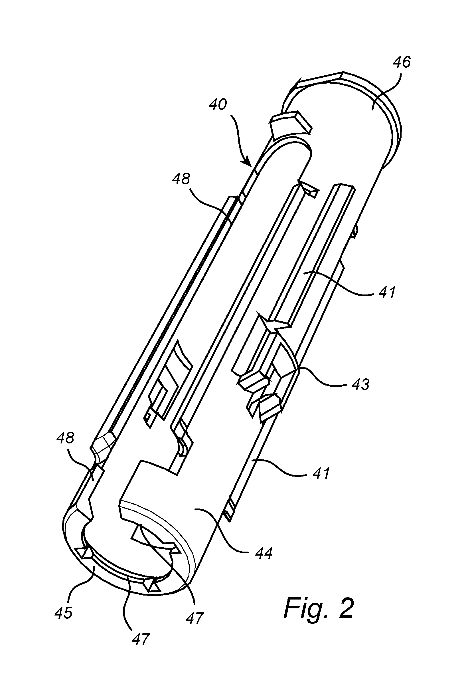
[0034]The autoinjector housing has the shape of a tube. The autoinjector housing is intended to house a pre-filled syringe 30 within a syringe holder 40. A drive mechanism (not shown) is also arranged within the housing. The drive mechanism is arranged to apply a proximally directed drive force to a movable plunger in the syringe in order to expel the drug through a needle(not shown).

[0035]The drive mechanism is not illustrated in detail in the...


PUM

PropertyMeasurementUnit
Diameteraaaaaaaaaa
Lengthaaaaaaaaaa

Abstract

The present invention relates to an autoinjector device (10) for use in combination with a syringe (30), said syringe comprising a movable plunger; a needle; and a tubular needle shield (34). The claimed autoinjector device (10) comprises: an elongated housing having a proximal (11) and a distal end (12); a drive mechanism; a syringe holder (40) in order to support the fragile syringe and to prevent damage to the syringe. The invention furthermore relates to a method for assembly of the autoinjector device according to the invention.

Description

FIELD OF THE INVENTION[0001]The present invention relates to an auto injection device for use in combination with a syringe, and a method for assembling said syringe in the autoinjector device.BACKGROUND OF THE INVENTION[0002]Different types of autoinjectors are frequently used in order to facilitate administration of drugs to patients. When the proximal end of the autoinjector is correctly positioned against the intended area of the skin of the patient, an activation means on the autoinjector is pressed in order to activate the autoinjector. When activated, a needle rapidly punctuates the skin and the drug is delivered via the needle automatically.[0003]There are two different categories of the autoinjectors on the market today. The first one uses custom designed medicament chambers, examples of these are described in WO2003 / 099358 and WO01 / 93926, while the second category uses standard pre-filled syringes. There are several advantages directed to the use of standard pre-filled syr...

Claims


Application Information

Patent Timeline
IPC IPC(8): A61M5/20A61M5/24
CPCA61M5/20A61M2005/206A61M5/24A61M5/2033Y10T29/49826A61M5/315A61M2005/2407A61M2005/244A61M5/3202A61M5/31A61M2207/00A61M2209/00
Inventor HOLMQVIST, ANDERS
Owner SHL MEDICAL AG
Learn More