

Self-braking descender with panic function
a descender and panic function technology, applied in the field of self-braking descenders with panic function, can solve problems such as difficulty in risk situations, and achieve the effects of preventing sharp descents, improving handling and reliability, and increasing braking
- Summary
- Abstract
- Description
- Claims
- Application Information
AI Technical Summary
Benefits of technology
Problems solved by technology
Method used
Image

Examples
Embodiment Construction
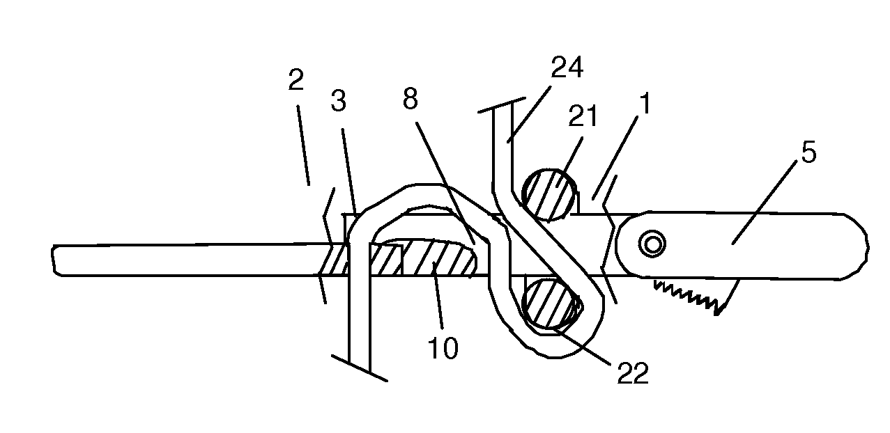
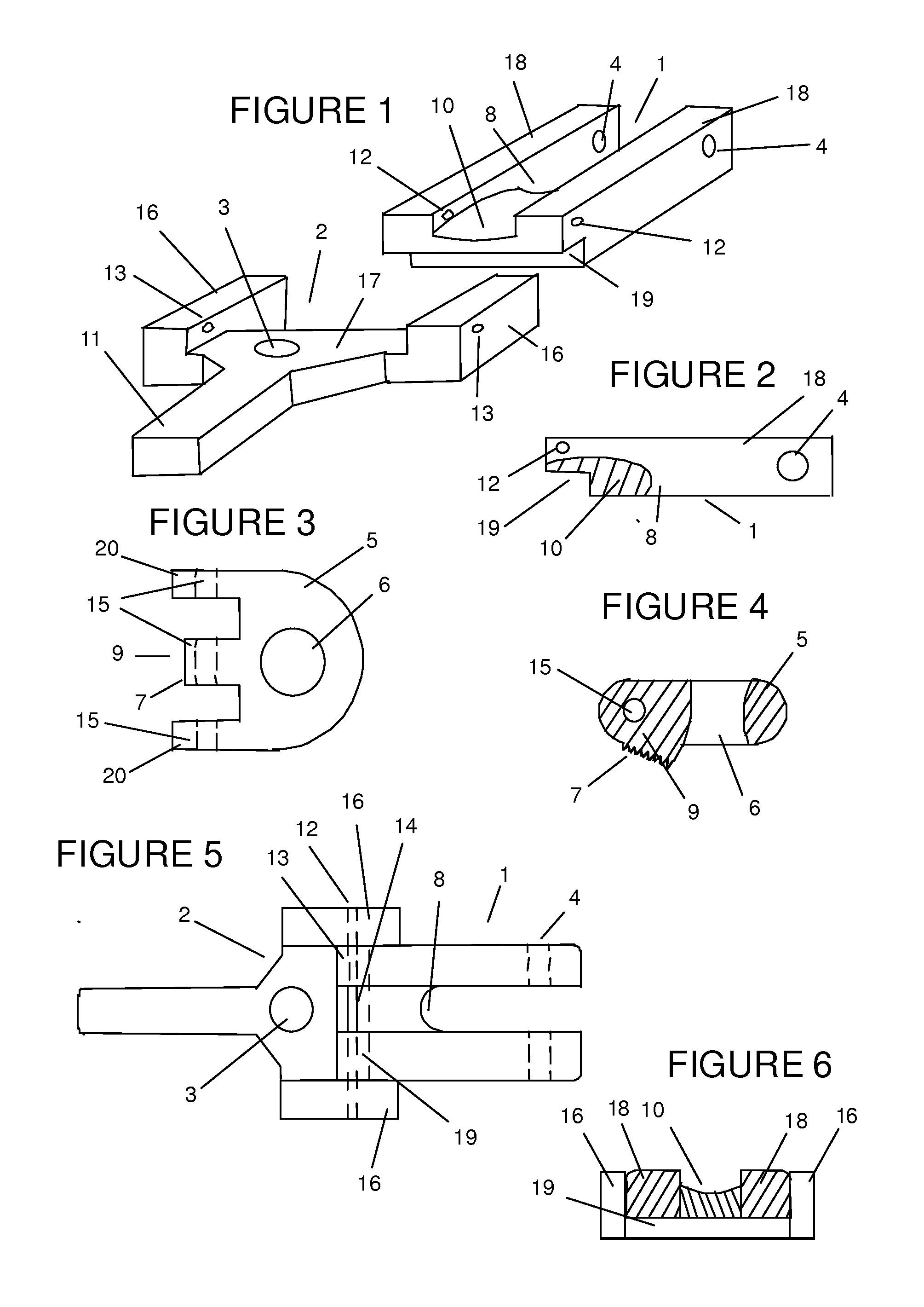
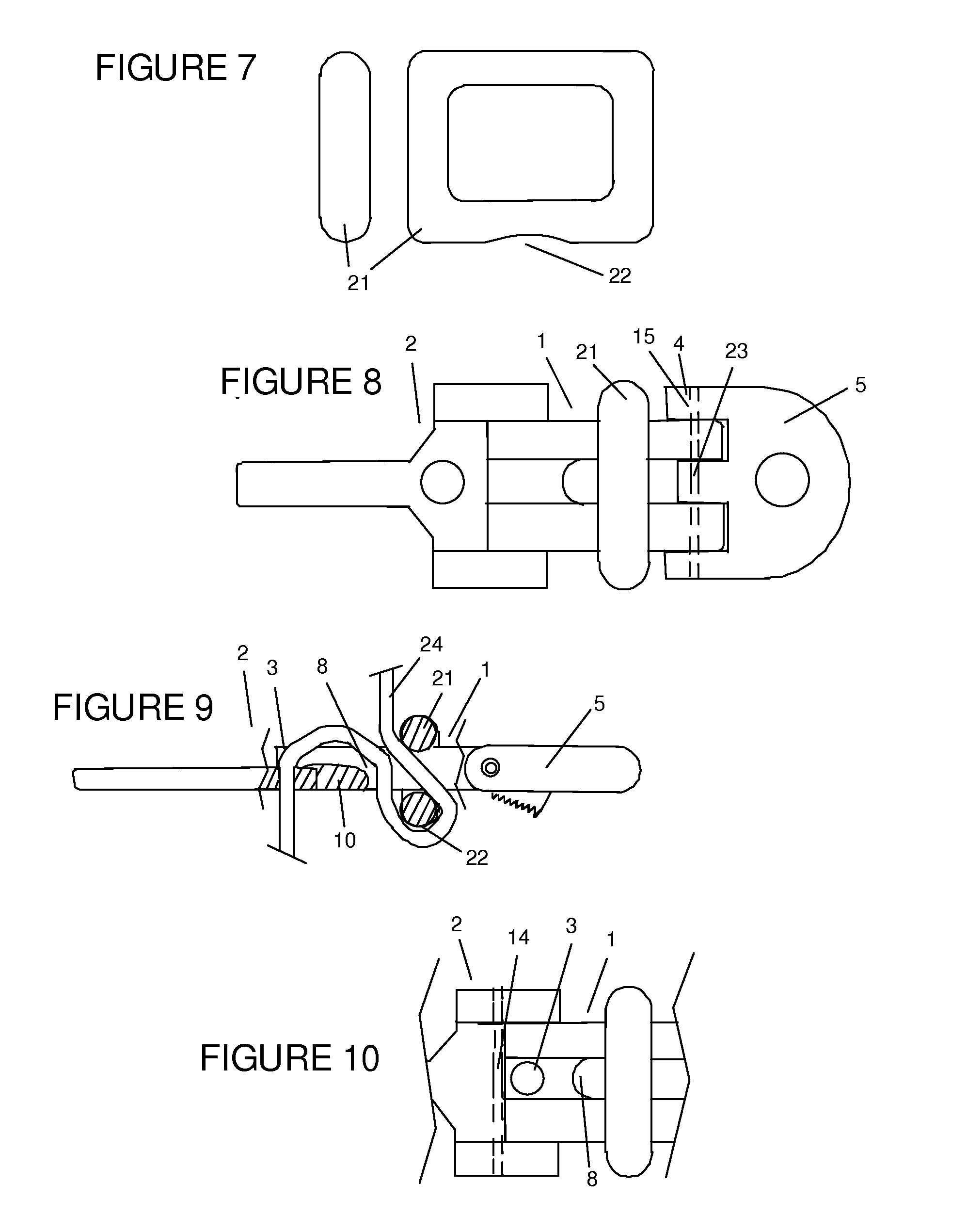
[0003]The invention presented below improves the descenders mentioned earlier and refers to a self-braking descender for cord with panic function, which is used to carry our descent operations on vertical walls and which improves the aforementioned elements. It has a self-braking function to prevent descent if the device is dropped and a panic function to prevent sharp descents if the user pulls too strongly on the descender, also allowing a smooth and progressive slide down the cord. The invention also allows cord to be released and taken up when the device is not under tension. The descender presented in this document is used fundamentally as a safety and escape system by the emergency services and has notable improvements in terms of ease of handling and reliability, two fundamental aspects in rescue situations.
[0004]The basis of the invention is a body which has a channel through which a cord can pass in two directions. One of the ends has a projecting piece or actuation lever w...
PUM
 Abstract
Description
Claims
Application Information