Protection apparatus, method and power supply system

Active Publication Date: 2014-10-23
ROBERT BOSCH GMBH
11 Cites 3 Cited by

AI-Extracted Technical Summary

Problems solved by technology

If such a hybrid or electric vehicle is serviced in a workshop, u...

Benefits of technology

[0017]In one embodiment, the signal generator comprises a controllable voltage source and/or a controllable current source. In addition, the first signal is a voltage pulse or a current pulse. If a controllable voltage source or a controllable current source is used in order to generate a voltage pulse or a current pulse as first signal, very flexible matching of the voltage protection apparatus to different application cases is possible.
[0018]In a further embodiment, the signal generator comprises a coil comprising a switching element, wherein the switching element is designed to connect the coil to a voltage source and to isolate the coil from the voltage source in order to generate the first signal in the form of a voltage pulse. If a coil is used as signal generator, a very simple design of the signal generator and therefore a very simple design of the protection apparatus is made possible.
[0019]In a further embodiment, the detection device comprises ...

Abstract

The present invention discloses a protection apparatus for an IT network having a first and a second live line, having a signal generator which is designed to feed a first signal to the first and/or to the second live line, having a detection device which is designed to detect the profile of the fed first signal in at least one live line, and having a control device which is designed to analyse the detected profile and to output a disconnection signal when the analysis of the detected profile indicates that a living organism is in contact with the first live line and the second live line. The present invention also discloses a method and a power supply system.

Application Domain

Technology Topic

EngineeringSignal generator +1

Image

  • Protection apparatus, method and power supply system
  • Protection apparatus, method and power supply system
  • Protection apparatus, method and power supply system

Examples

  • Experimental program(1)

Example

[0030]Identical or functionally identical elements and apparatuses, where not specified otherwise, have been provided with same reference symbols in all of the figures.
DETAILED DESCRIPTION
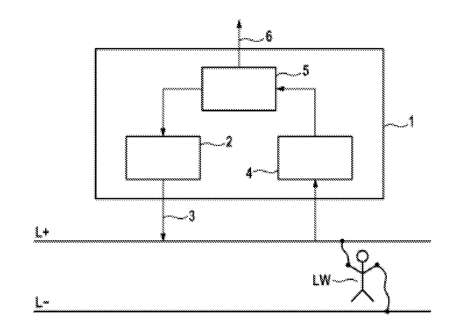
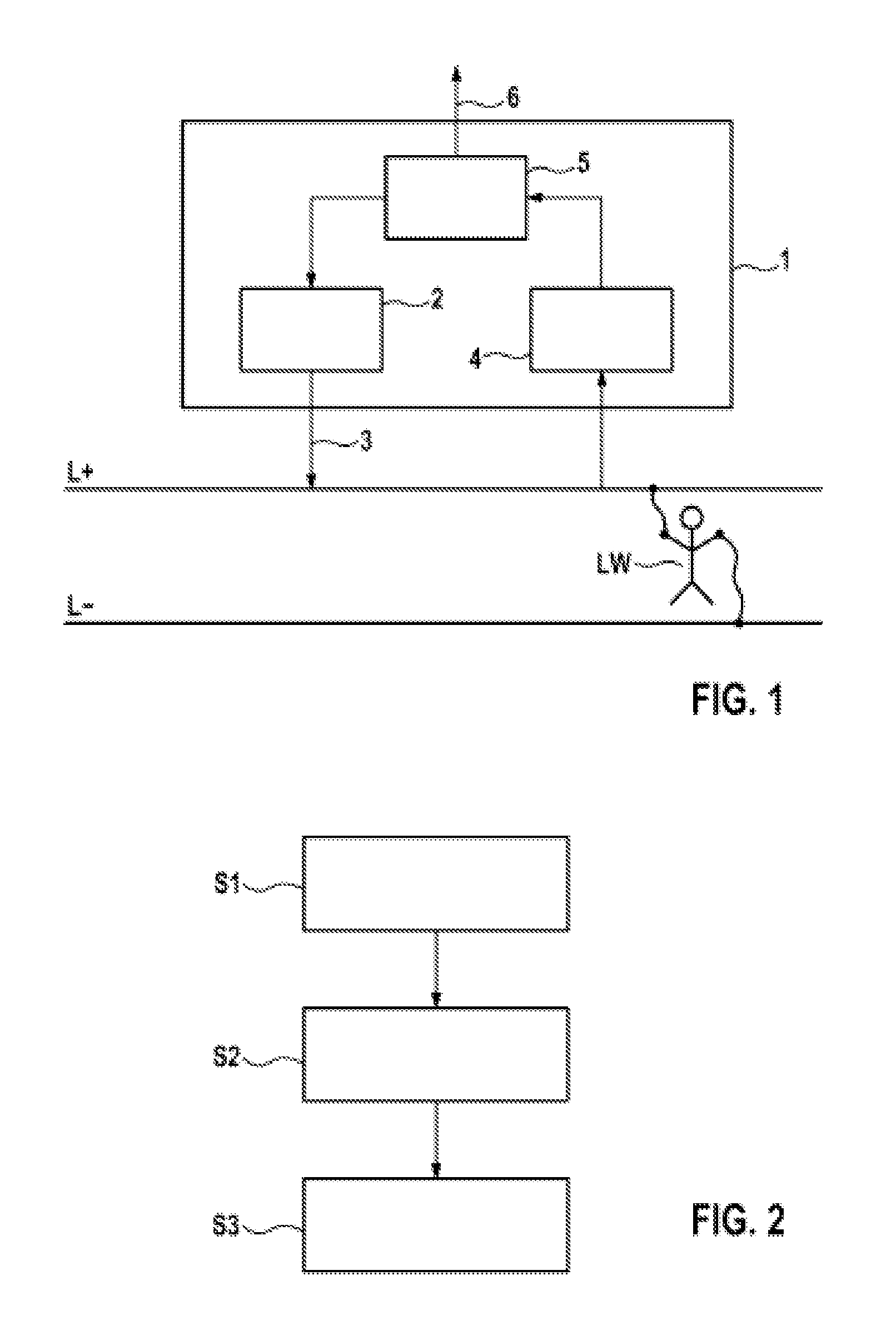
[0031]FIG. 1 shows a block diagram of an embodiment of a protection apparatus 1 according to the invention.
[0032]The protection apparatus 1 in FIG. 1 comprises a signal generator 2, which is coupled to a control device 5 and which is controlled by the control device 5. In addition, the protection apparatus 1 comprises a detection device 4, which is designed to detect a characteristic of a signal in the live lines L+, L− and to provide this signal to the control device 5. In addition, the control device 5 is designed to output a disconnection signal 6.
[0033]Finally, FIG. 1 comprises two live lines L+, L− of an IT grid, each of which lines is touched by a hand of a living organism LW, which is represented in the form of a stick man LW. The signal generator 2 is coupled to the live line L+in order to feed a first signal 3 into said line, and the detection device 4 is coupled to the live line L+ in order to detect the characteristic of the fed-in signal in the live line L+.
[0034]The control device 5 in FIG. 1 is in the form of a microcontroller 5, which runs a computer program product which provides the desired functionality. In further embodiments, the control device 5 can be in the form of an application-specific integrated circuit 5 or the like.
[0035]In yet further embodiments, the control device 5 comprises a CAN bus interface or a FlexRay interface, via which the control device 5 can transmit data relating to the identification of a living organism to a further vehicle control device. As a result, for example, further actions can be initiated in the vehicle, such as, for example, the initiating of an emergency call or the disconnection of the internal combustion engine.
[0036]FIG. 2 shows a flow chart of an embodiment of a method according to the invention.
[0037]In a first step S1, a first signal 3 is fed into the first and/or the second live line L+, L−. In a second step S2, the characteristic of the fed-in first signal 3 in the at least one live line L+, L− is detected. Finally, in a third step S3, the detected characteristic is analyzed and a disconnection signal 6 is output when the analysis of the detected characteristic indicates that the first live line L+ and the second live line L− are being touched by a living organism LW.
[0038]FIG. 3 shows a block diagram of an embodiment of a power supply system according to the invention.
[0039]The power supply system in FIG. 3 comprises a battery B, which is coupled electrically to a contactor SV via two live lines L+, L−, which contactor is designed to interrupt the two live lines. The contactor is coupled to a capacitor of a high-voltage intermediate circuit via the two live lines L+, L−.
[0040]In addition, FIG. 3 comprises a protection apparatus 1, which is coupled to the high-voltage intermediate circuit ZK.
[0041]In contrast to FIG. 1, the signal generator 2 in FIG. 3 comprises a coil 7 and a switching element 8, which is designed to couple the coil 7 to a voltage source (not shown) and to isolate the coil 7 from the voltage source, and which is controlled by the control device 5. The isolation of the coil 7 from the voltage source results in, owing to the inductance of the coil 7, a voltage pulse being fed into the line L− of the power supply system.
[0042]In addition, the detection device 4 in FIG. 4 comprises a voltage and current sensor 9, which is designed to detect values for the voltage and values for the current intensity in the live line L− and to provide the detected values to the control device 5. The control device 5 has an analog-to-digital converter 11 in order to digitize the values detected by the voltage sensor and current sensor 9. The digitized values are thereupon stored in a memory 12 in order to store the characteristic of the voltage and the characteristic of the current intensity in the live line L−. A transformation device 13 thereupon transforms the stored characteristics from the time range into the frequency range. This is performed in particular by means of a fast Fourier transform. Finally, the evaluation device 14 analyzes the transformed characteristics in the frequency range and identifies those frequencies at which the impedance of the live lines has local minima. The evaluation device 14 is further designed to output the disconnection signal 6 when at least one of the identified frequencies is in at least one predetermined frequency range for identification of a living organism LW. If the disconnection signal 6 is output, the contactor SV isolates the two live lines L+, L−. from the battery B.
[0043]The predetermined frequency range can be between 0 Hz and 1 MHz . If a human is intended to be identified as the living organism, the frequency range can be in particular between 1 kHz and 100 kHz .
[0044]In this case, the impedance is calculated according to Ohm's Law in accordance with the formula Z=U/I.
[0045]In further embodiments, the detection device 4 can comprise a shunt resistor or a contactless current sensor.
[0046]FIG. 4 shows a circuit diagram illustrating the electrical equivalent circuit of a human.
[0047]The equivalent circuit for a human, as illustrated in FIG. 4, is prescribed by the standard IEC 60850, IEC 61010.
[0048]The equivalent circuit comprises a parallel circuit comprising a resistor Rs and a capacitor Cs and, in series therewith, a resistor Rb, with a resistor R1 in series with a capacitor C1 being connected in parallel with said resistor Rb.
[0049]In accordance with the standard IEC 60850, IEC 61010, the resistor Rs has a resistance value of 1 kohm, the capacitor Cs has a capacitance of 0.22 μF, the resistor Rb has a resistance value of 500 ohms, the resistor R1 has a resistance value of 10 kohms, and the capacitor C1 has a capacitance of 0.022 μF.
[0050]On the basis of this equivalent circuit diagram, it is possible to calculate the frequency at which the equivalent circuit has a minimum impedance. This frequency corresponds to the resonant frequency of the illustrated equivalent circuit diagram and therefore also to the resonant frequency of the human body.
[0051]FIG. 5 shows a graph illustrating a frequency-dependent impedance.
[0052]In the basic graph shown in FIG. 5, an impedance Z is plotted on the y axis. The frequency is plotted on the x axis of the graph. In the graph, an impedance curve is also plotted, which impedance curve has a characteristic from 0 Hz up to approximately 1 MHz at a high impedance determined by parasitic effects. The impedance curve has, for an exemplary design, a first minimum, for example at the frequency 1 kHz of approximately 0.4 ohm and a second minimum, which is much less pronounced, of around 30 kHz, for example.
[0053]The frequency at which the first minimum occurs, corresponds to the resonant frequency of the resonant circuit comprising the intermediate circuit capacitor C and the parasitic resistances between the battery B and the intermediate circuit capacitor C.
[0054]The frequency at which the second minimum of the impedance curve occurs, corresponds to the resonant frequency of the equivalent circuit illustrated in FIG. 4. Merely the presence of the second minimum makes it possible for the evaluation device to establish that a living organism is touched in the two live lines L+, L−. The absolute value of the impedance at this frequency is not critical.
[0055]Although the present invention has been described above with reference to preferred exemplary embodiments, it is not restricted to these exemplary embodiments, but can be modified in a variety of ways. In particular, the invention can be altered or modified in various ways without departing from the essence of the invention.

PUM

no PUM

Description & Claims & Application Information

We can also present the details of the Description, Claims and Application information to help users get a comprehensive understanding of the technical details of the patent, such as background art, summary of invention, brief description of drawings, description of embodiments, and other original content. On the other hand, users can also determine the specific scope of protection of the technology through the list of claims; as well as understand the changes in the life cycle of the technology with the presentation of the patent timeline. Login to view more.

Similar technology patents

Craft apron

InactiveUS7636949B1Minimizes fuzzing and pillingSimple designConvertible garmentLuggageFastenerEngineering
Owner:SHOOSHAN MARY E

Classification and recommendation of technical efficacy words

  • Simple design
  • Easily detect

Methods and apparatus for femoral and tibial resection

InactiveUS20050055028A1Simple designPrecise and accurate in operationJoint implantsNon-surgical orthopedic devicesFemurCutting guide
Owner:PUGET BIOVENTURES

Interactive Hi-Tech doll

InactiveUS20070128979A1More magicalEasily detectDollsComputerized toysCuriosityFacial expression
Owner:J SHACKELFORD ASSOCS

Therapeutic sock for diabetics

InactiveUS20070283483A1Easily detectPhysical therapyInsolesBiomedical engineeringFiber
Owner:SOCKWISE
Why Eureka
Try Eureka