Imaging lens
- Summary
- Abstract
- Description
- Claims
- Application Information
AI Technical Summary
Benefits of technology
Problems solved by technology
Method used
Image

Examples
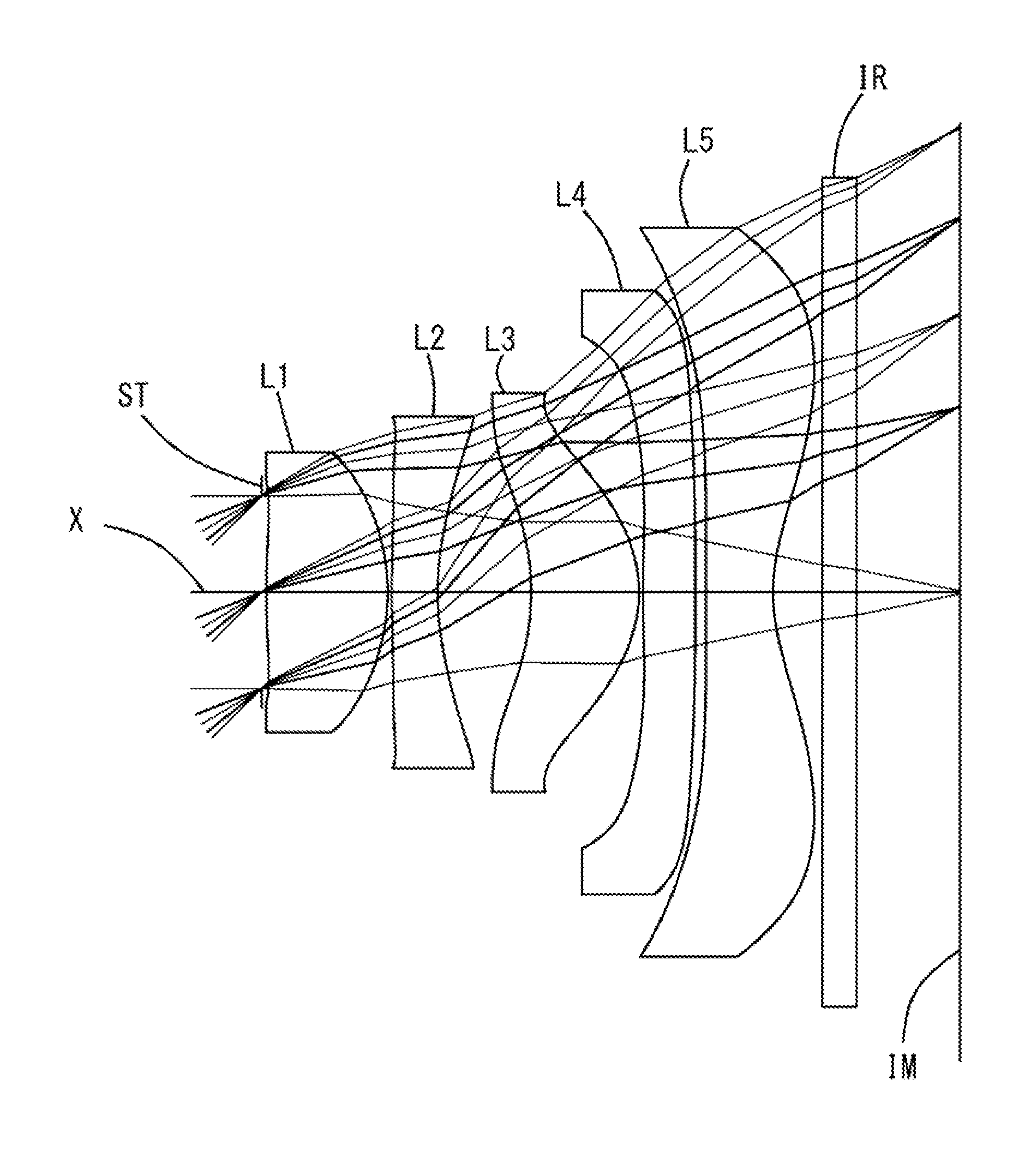
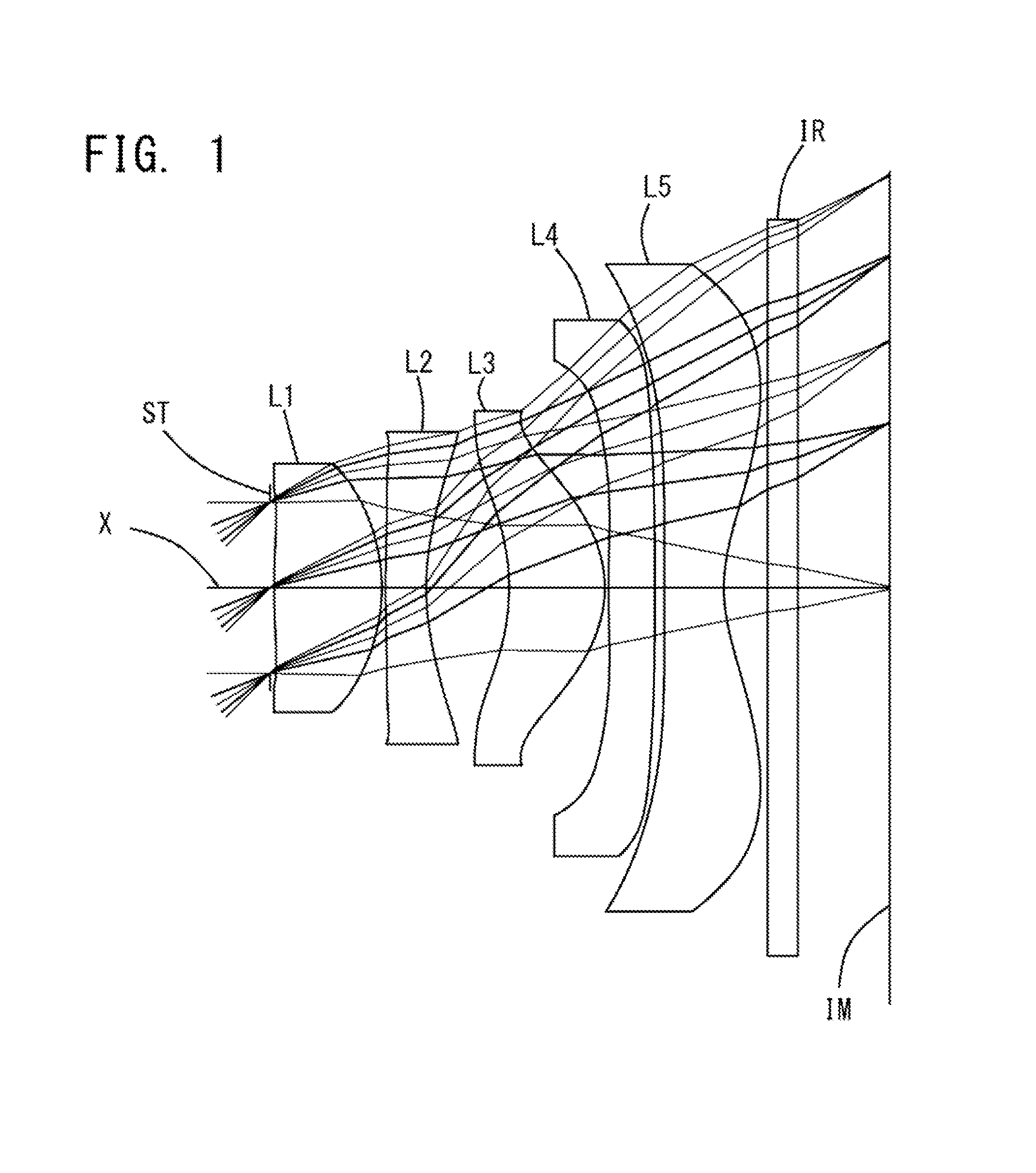
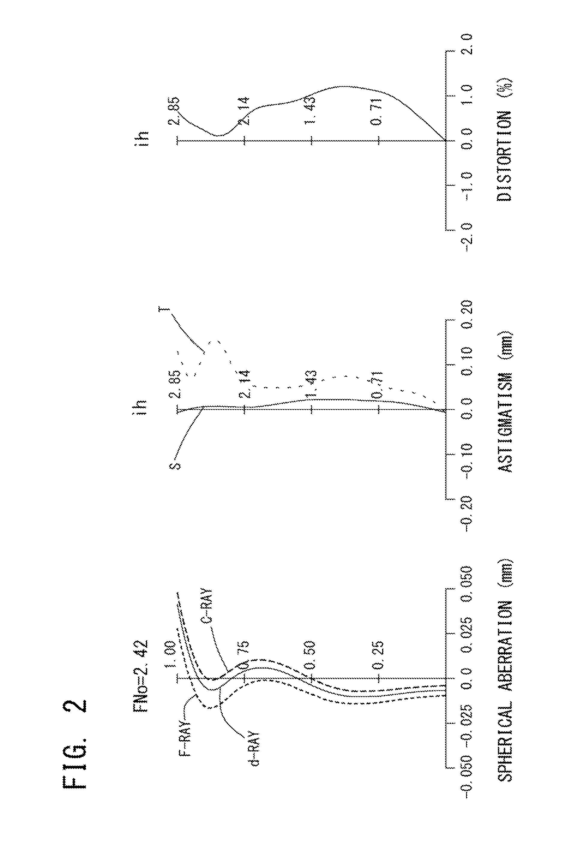
example 1
[0087]The basic lens data of Example 1 is shown below in Table 1.
TABLE 1Example 1in mmf = 2.86Fno = 2.42ω(°) = 44.7ih = 2.85Surface DataCurvatureSurfaceRefractiveAbbeSurface No. iRadius rDistance dIndex NdNumber vd(Object Surface)InfinityInfinity 1 (Stop)Infinity0.030 2*5.3760.7431.54455.57 3*−1.2640.026 4*8.2200.2801.63523.91 5*1.7010.573 6*−1.5470.6611.54455.57 7*−0.8300.025 8*6.3150.3191.53556.16 9*106.9640.06610*45.5400.4121.53556.1611*1.1200.30012Infinity0.2101.51764.2013Infinity0.637Image PlaneInfinityConstituent Lens DataLensStart SurfaceFocal Length121.95924−3.431362.4854812.539510−2.154Aspheric Surface Data2nd Surface3rd Surface4th Surface5th Surface6th Surfacek0.000E+00−1.067E+010.000E+00−9.535E+003.921E−01A4−5.481E−02−5.007E−01−1.097E−012.929E−036.196E−02A6−6.553E−017.506E−01−5.797E−024.613E−02−8.947E−02A81.673E+00−1.373E+003.750E−01−1.081E−014.402E−01A10−2.072E+001.824E+00−2.876E−011.273E−01−1.945E−01A120.000E+00−1.175E+004.022E−02−5.342E−02−2.097E−01A140.000E+000.000E+0...
example 2
[0091]The basic lens data of Example 2 is shown below in Table 2.
TABLE 2Example 2in mmf = 2.86Fno = 2.42ω(°) = 44.7ih = 2.85Surface DataCurvatureSurfaceRefractiveAbbeSurface No. iRadius rDistance dIndex NdNumber vd(Object Surface)InfinityInfinity 1 (Stop)Infinity0.021 2*5.4170.7421.54455.57 3*−1.2690.025 4*7.5990.2801.63523.91 5*1.6610.558 6*−1.4840.6441.54455.57 7*−0.8650.025 8*3.2610.3151.53556.16 9*4.2540.06210*7.2790.4101.53556.1611*1.20870.30012Infinity0.2101.51764.2013Infinity0.683Image PlaneInfinityConstituent Lens DataLensStart SurfaceFocal Length121.96824−3.406362.7894823.544510−2.776Aspheric Surface Data2nd Surface3rd Surface4th Surface5th Surface6th Surfacek0.000E+00−1.090E+010.000E+00−9.511E+002.626E−01A4−6.441E−02−4.927E−01−1.100E−013.777E−031.060E−01A6−6.054E−017.384E−01−5.458E−025.149E−02−1.048E−01A81.635E+00−1.369E+003.684E−01−1.095E−014.312E−01A10−2.117E+001.826E+00−2.901E−011.176E−01−1.929E−01A120.000E+00−1.176E+004.037E−02−4.986E−02−2.099E−01A140.000E+000.000E+000...
example 3
[0095]The basic lens data of Example 3 is shown below in Table 3.
TABLE 3Example 3in mmf = 2.86Fno = 2.42ω(°) = 44.8ih = 2.85Surface DataCurvatureSurfaceRefractiveAbbeSurface No. iRadius rDistance dIndex NdNumber vd(Object Surface)InfinityInfinity 1 (Stop)Infinity0.020 2*5.3990.7441.54455.57 3*−1.2670.025 4*7.9530.2801.63523.91 5*1.6830.558 6*−1.4580.6321.54455.57 7*−0.8820.025 8*3.0540.3411.53556.16 9*3.7750.06910*6.9190.4101.53556.1611*1.2580.33712Infinity0.2101.51764.2013Infinity0.624Image PlaneInfinityConstituent Lens DataLensStart SurfaceFocal Length121.96524−3.418362.9644825.671510−2.951Aspheric Surface Data2nd Surface3rd Surface4th Surface5th Surface6th Surfacek0.000E+00−1.070E+010.000E+00−9.522E+002.510E−01A4−6.215E−02−4.916E−01−1.099E−011.952E−031.112E−01A6−6.172E−017.376E−01−5.274E−025.299E−02−1.049E−01A81.641E+00−1.370E+003.689E−01−1.080E−014.323E−01A10−2.092E+001.833E+00−2.903E−011.174E−01−1.902E−01A120.000E+00−1.176E+004.039E−02−5.078E−02−2.099E−01A140.000E+000.000E+000....
PUM
 Abstract
Description
Claims
Application Information
 - R&D Engineer
- R&D Manager
- IP Professional
- Industry Leading Data Capabilities
- Powerful AI technology
- Patent DNA Extraction
Browse by: Latest US Patents, China's latest patents, Technical Efficacy Thesaurus, Application Domain, Technology Topic.
© 2024 PatSnap. All rights reserved.Legal|Privacy policy|Modern Slavery Act Transparency Statement|Sitemap