
Light emitting diode (LED) light tube

a technology of light-emitting diodes and light-emitting diodes, which is applied in the direction of elongated light-emitting devices, semiconductor devices of light sources, light-emitting devices, etc., can solve the problems of large amount of molded compounds, large amount of materials, and high manufacturing costs, so as to shorten the manufacture time and reduce the cost of materials. , the effect of reducing the cost of materials

Inactive Publication Date: 2014-10-23
GEM WELTRONICS TWN CORP
View PDF13 Cites 11 Cited by
  • Summary
  • Abstract
  • Description
  • Claims
  • Application Information

AI Technical Summary

Benefits of technology

The present invention provides an LED light tube with high brightness and reduced manufacturing time. It reduces the cost of material and simplifies the manufacturing process. The LED dies are arranged densely by shortening the distance between adjacent pairs, allowing an appropriate adjustment. The LED light tube can be made in different lengths according to user requirements, reducing material cost and simplifying manufacturing process.

Problems solved by technology

The preceding several processes and assembly process and several structure of the LED units and the printed circuit plate are in fact not directly related to the LED light tube so that an overall manufacturing cost thereof cannot be reduced, thereby causing a relatively large amount of materials.
It is noticed that a large amount of molded compound consisting of fluorescent glue is required to conduct the molded process.
The manufacturing cost is therefore high and consequently results in long manufacturing time.

Method used


Image

  • Light emitting diode (LED) light tube
  • Light emitting diode (LED) light tube
  • Light emitting diode (LED) light tube

Examples


first embodiment

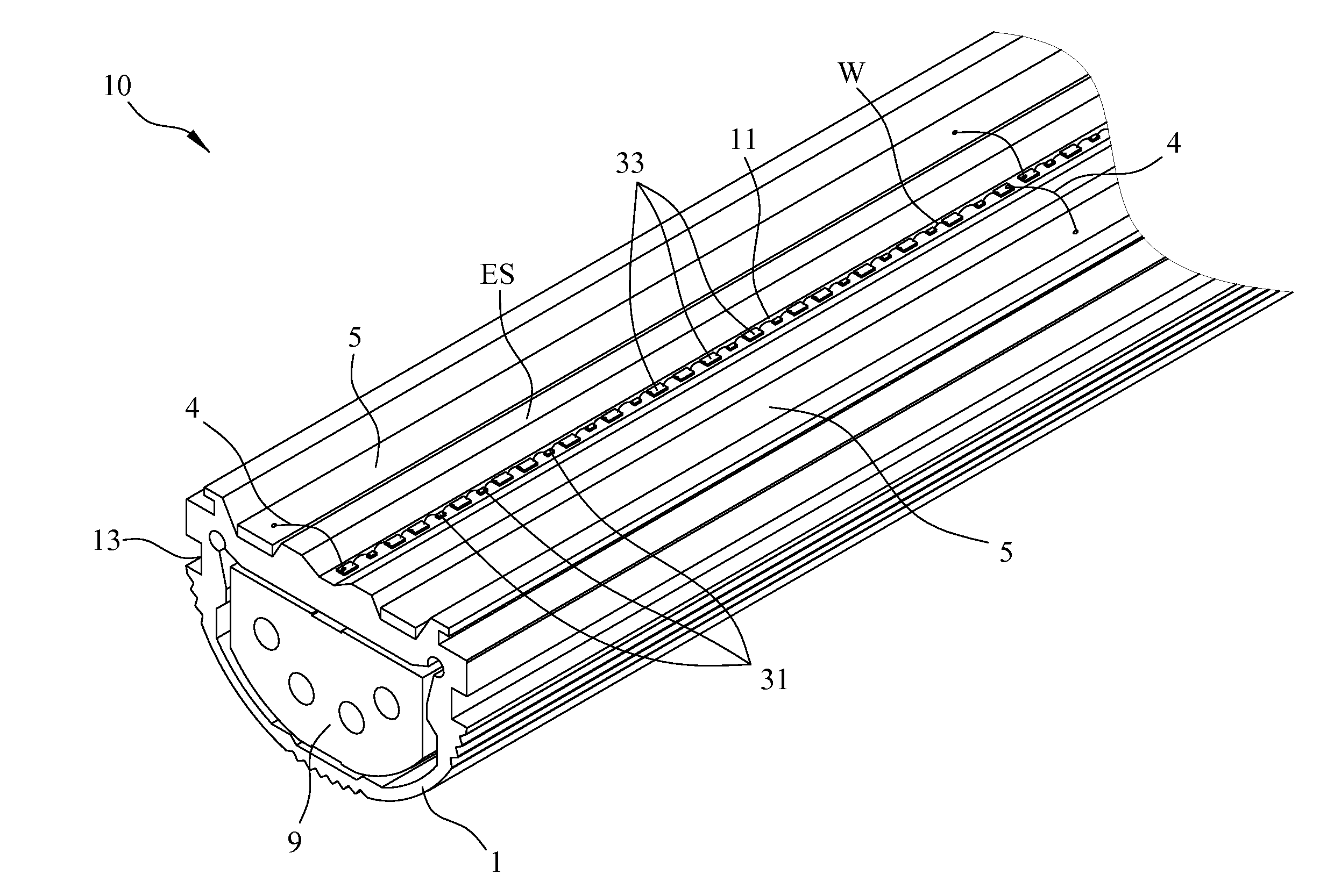
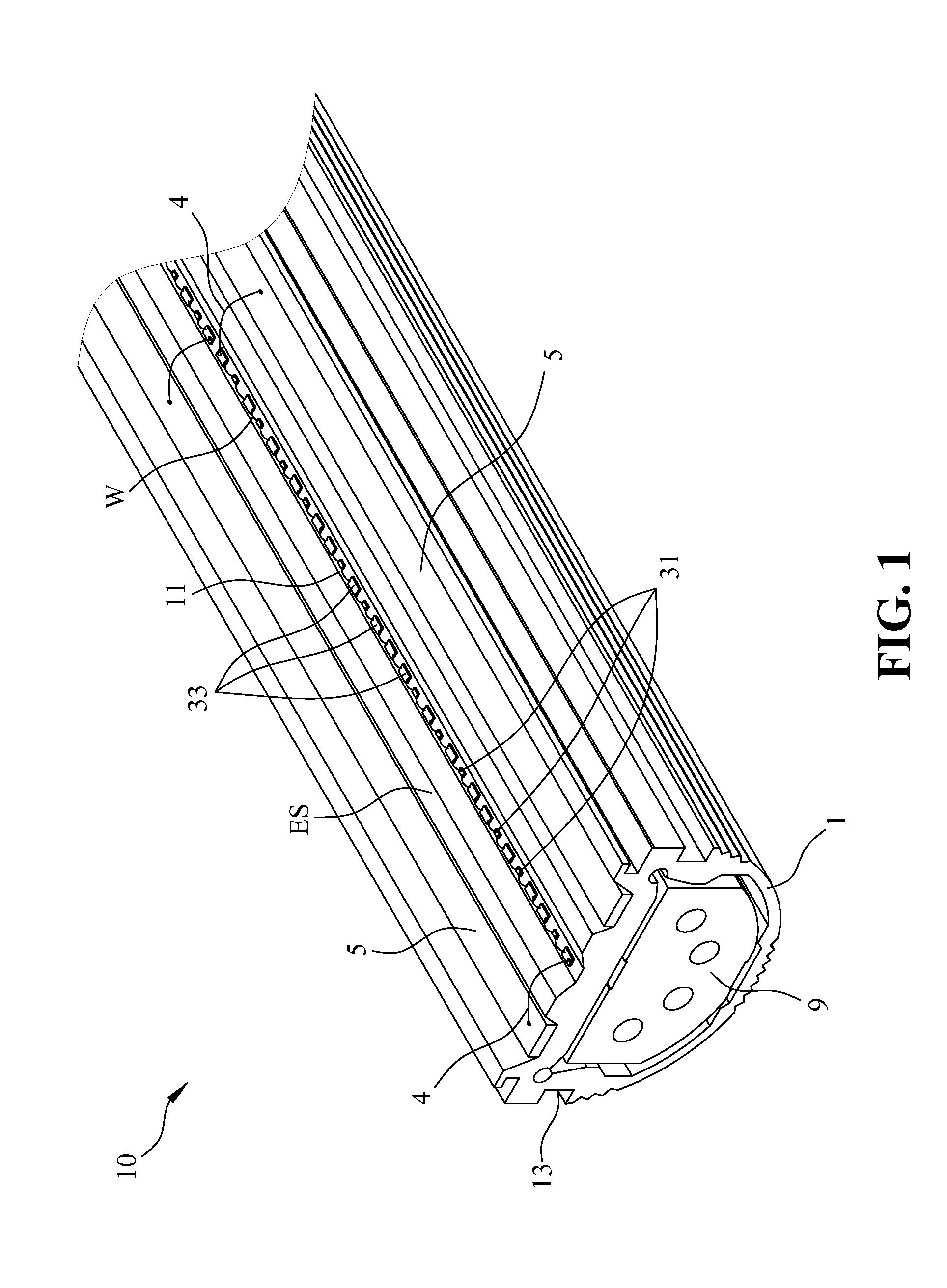
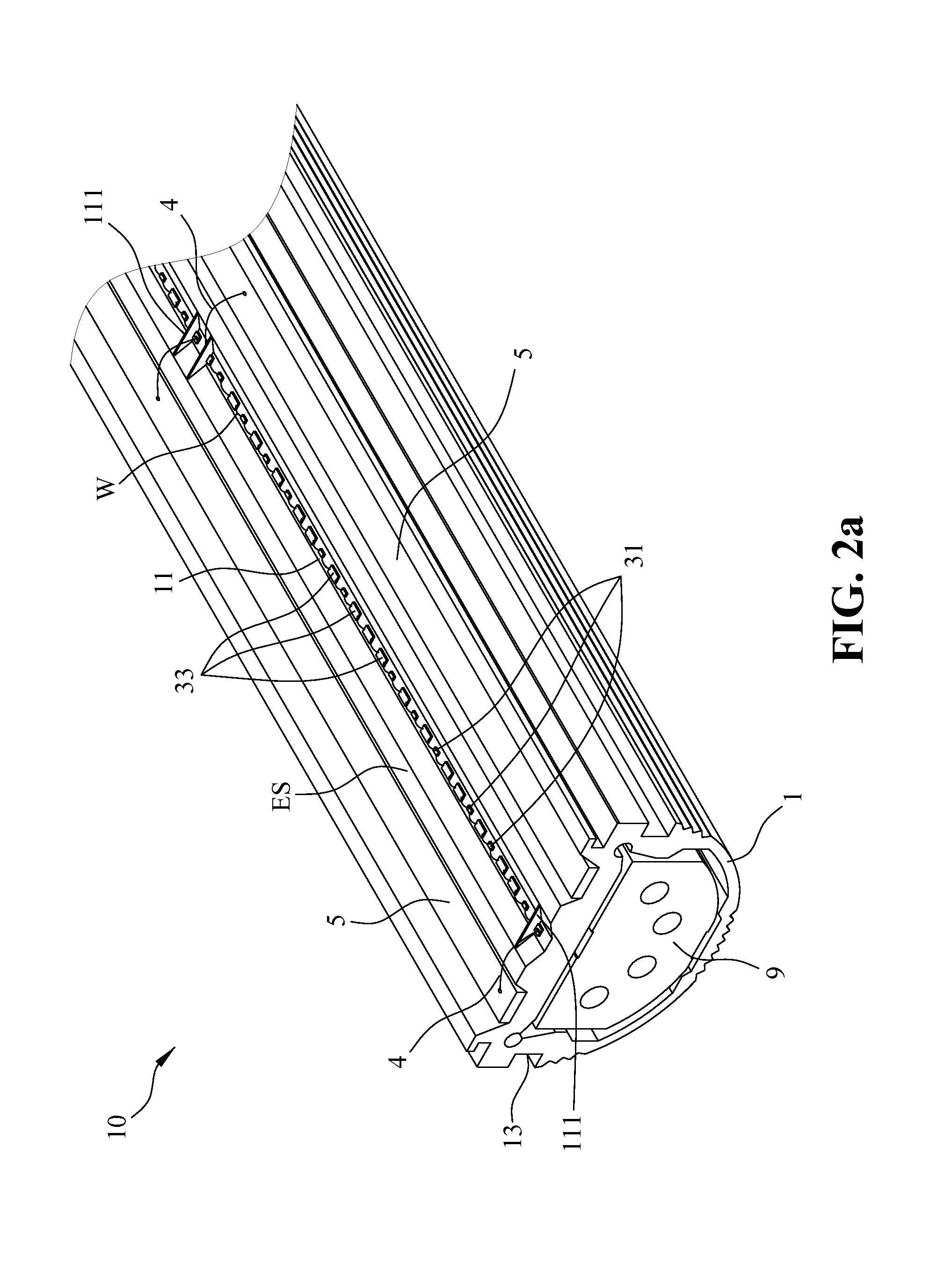
[0032]Referring to FIGS. 2A-2C, wherein FIG. 2A is the integrally formed LED light tube of the present invention, FIG. 2B is a top planar view of FIG. 2A and FIG. 2C is a cross-sectional view of FIG. 2A. As illustrated, the LED light tube 10 of the present invention further includes at least two partition walls 111 formed transversely in the recess 11 at two opposite ends thereof and exposing two of the conductive elements 33 respectively adjacent to the opposite ends. These two conductive elements 33 are connected electrically to the circuit units 5 via the external connectors 4 as described in the above manner. Note that arrangement of the LED dies 31 in FIG. 2A is different from FIG. 2B, in which the LED dies 31 are laid out in linear array manner with only two conductive elements 33 at opposite ends of the recess.

second embodiment

[0033]FIG. 3 shows the integrally formed LED light tube of the present invention. Also referring to FIG. 2C, the LED light tube in this embodiment is similar to the previous one in structure, except an optical layer 100 extending between the partition walls 111 and covering the LED dies 31 and the conductive elements 33 so as to provide optical effects, such as color mixing for the light emitted from the LED dies 31. The optical layer 100 is preferably made from fluorescent glue or material mixture consisting of fluorescent glue and silicon resin. The LED light tube 10 of the present invention further includes a protection layer 200 covering the optical layer 100 so as to isolate the vapor and dust from getting interior of the optical layer 100, thereby damaging the optical effects provided by the layer 100. Preferably, the protection layer 200 is mainly made from silicon resin.

[0034]FIG. 4A shows one form of the recess 11 in a heat dissipation base 1 employed in the integrally form...


PUM


Abstract

A Light Emitting Diode (LED) light tube includes a heat dissipation base having a light emitting side formed with a recess and at least one illumination unit and a bridging unit disposed on a bottom surface of the recess. The illumination unit and the bridging unit are connected electrically relative to each other via wire-bond technique. Two circuit units are disposed on the light emitting side of the heat dissipation base respectively located at two opposite sides of the recess.

Description

BACKGROUND OF THE INVENTION[0001]1. Field of the Invention[0002]The present invention relates to a Light Emitting Diode (LED) light tube, more particularly to an LED light tube having a heat dissipation base formed with a recess, in which, an illumination unit and a bridging unit are formed integrally on a bottom surface of the recess.[0003]2. Description of the Prior Art[0004]Owing to high efficient, long lasting, small size, low energy consuming, swift in response, and mature advance in the modern electronics lately, a majority of traditional bulbs or tubes are gradually replaced by LED light tubes.[0005]A prior art LED light tube generally includes a light tube, a heat dissipation plate, a printed circuit board, a plurality of LED units and two electrodes. The heat dissipation plate is mounted within the light tube while the printed circuit board is mounted on the heat dissipation plate. The LED units are connected electrically with the printed circuit board.[0006]During the asse...

Claims


Application Information

Patent Timeline
Patent Type & Authority Applications(United States)
IPC IPC(8): F21V29/00
CPCF21V29/22F21V29/70F21V23/00F21V23/003F21S4/28H01L2224/48091H01L2224/48137F21Y2103/10F21Y2115/10H01L2224/45144H01L2924/00014H01L2924/00
Inventor HWU, JON-FWUWU, YUNG-FULIU, KUI-CHIANG
Owner GEM WELTRONICS TWN CORP
Learn More